Table of Contents
Advertisement
Advertisement
Table of Contents

Related Manuals for Moog G392-004


Summary of Contents for Moog G392-004
- Page 1 MSD Servo Drive AC-AC Operation Manual Single-Axis System AC-AC 4 A to 450 A...
- Page 2 Valid from firmware status: V2.20-01 Information and specifications may be changed at any time. For information on the The German version is the original version of the operation manual. latest version please refer to drives-support@moog.com.
- Page 3 Guide through this document Dear user! We are happy that you have made a decision in favour of a product from Moog GmbH. In order to be able to start operation of your new MSD Servo Drive AC-AC quickly and without problems, we ask you kindly to read this operation manual thoroughly...
- Page 4 Id. no.: CA65642-001 Date: 03/2012 moog MSD Servo Drive AC-AC Operation Manual Order Code G395 - The order designation G392-xxx-xxx-xxx and G395-xxx-xxx-xxx informs you about the corresponding variant of the servo drive delivered to you. The significance of the individual characters of the order designation is given in the following order code. You Rated current will find a complete order code with all values in the MSD Servo Drive AC-AC Ordering...
- Page 5 MOOG Warning symbols (see also section 1.1) S/N : D116605 Rev. A D-71034 Böblingen 230 V AC 3ph, 50/60 Hz www .moog.com/industrial ATTENTION! Misoperation may cause damage to or malfunction of the Made in Germany 4,0 A drive. Year of production...
- Page 6 Id. no.: CA65642-001 Date: 03/2012 moog MSD Servo Drive AC-AC Operation Manual Space for personal notes...
-
Page 7: Table Of Contents
...............30 4.2.2 Connection between PC and servo drive .............44 3.7.6 Terminal diagram precharge (only Size 7) .............30 4.2.3 Parameter setting ..................44 4.2.4 Drive control with Moog D 5 ..........44 rive DministrAtor moog MSD Servo Drive AC-AC Operation Manual Id. no.: CA65642-001 Date: 03/2012... - Page 8 Id. no.: CA65642-001 Date: 03/2012 moog MSD Servo Drive AC-AC Operation Manual Serial commissioning ....................46 Technical data MSD Servo Drive AC-AC..............64 Integrated control unit and MMC-card ..............47 A.2.1 G392-004A to G392-016, air-cooled ............64 4.4.1 Function of buttons T1 and T2 ..............48 A.2.2 G392-020 to G392-072, air-cooled..............65 4.4.2 Display ......................48...
-
Page 9: Safety
• Comply with the standards for electrical installation, such as wire cross- section, PE-conductor and ground connection. • Do not touch electronic components and contacts (electrostatic discharge may destroy components). Table 1.1 Notes on safety moog MSD Servo Drive AC-AC Operation Manual Safety Id. no.: CA65642-001 Date: 03/2012... -
Page 10: Intended Use
Repairs must only be carried out by authorised repair workshops. unauthorised opening Warning symbols General explanation ANSI Z 535 and incorrect intervention could lead to physical injury or material damage. The warranty granted by Moog GmbH will become null and void. ATTENTION! Misoperation may This may result in physical injury or... -
Page 11: Mechanical Installation
Maximum pollution severity 2 in accordance with EN 60664-1. Further information on environmental conditions can be found in table A.16 in the appendix. If you require further detailed information on installation you should consult the Moog Helpline (see page 54). -
Page 12: Dimensions On Devices With Air Cooling
Id. no.: CA65642-001 Date: 03/2012 moog MSD Servo Drive AC-AC Operation Manual 2.2.1 Dimensions on devices with air cooling MSD Servo Drive Size 1 Size 2 Size 3 Size 4 Size 5 Size 6 Size 6A AC-AC Weight [kg] B (Width) 58.5 H (Height) T (Depth) 29.25 344.5 D Ø Screws 2 x M4 4 x M4 4 x M5... - Page 13 Size 2 ... Size 6A Size 1 H1 H Fig. 2.2 Dimensional drawing of housing with air cooling, schematic representation for Size 1 to Size 6A moog MSD Servo Drive AC-AC Operation Manual Mechanical installation Id. no.: CA65642-001 Date: 03/2012...
-
Page 14: Dimensions On Devices With Liquid Cooling
Id. no.: CA65642-001 Date: 03/2012 moog MSD Servo Drive AC-AC Operation Manual 2.2.2 Dimensions on devices with liquid cooling NOTE: The minimum distance “E” specified in the table applies for devices with the same power. When butt mounting devices with different drive MSD power you should arrange the devices according to their power (e.g. viewed Servo Drive ... - Page 15 H1 H Fig. 2.5 Dimensional drawing of housing with liquid cooling, schematic representation for Size 7 Fig. 2.4 Dimensional drawing of housing with liquid cooling, schematic representation for Size 3 to Size 6A moog MSD Servo Drive AC-AC Operation Manual Mechanical installation Id. no.: CA65642-001 Date: 03/2012...
-
Page 16: Connection Of Cooling Circuit
Id. no.: CA65642-001 Date: 03/2012 moog MSD Servo Drive AC-AC Operation Manual 2.2.3 Connection of cooling circuit NOTES: • Scope of supply Depending on size the MSD Servo Drive AC-AC has a liquid coolant capacity of up Positions 2 to 5 are not contained in the scope of supply and must be to 0.5 l. -
Page 17: Installation
X11) and missing control supply (+24 V on X9/X10 or X44)! Additional information can be found in the corresponding connection description. If you require further detailed information on installation you should consult the Moog The following general guidelines apply for the installation of single-axis servo drives: Helpline (see page 54). -
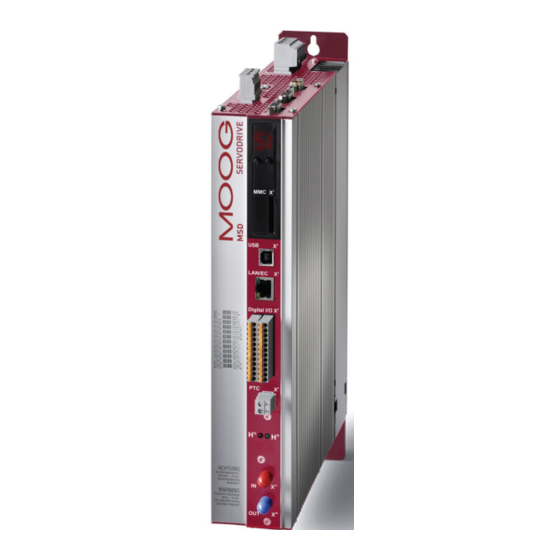
Page 18: Overview Of Connections Size 1 To Size 4
Id. no.: CA65642-001 Date: 03/2012 moog MSD Servo Drive AC-AC Operation Manual 3.2 Overview of connections Size 1 to Size 4 Step Action Comment The following shows the layout with the corresponding positions of plugs and terminals. Section 3.2 for Size 1 to Size 4 Determine the pin assignment for your Section 3.3 for Size 5 to Size 6A... - Page 19 Hardware name plate page 4 Option 1 Field buses Brake (-) Software name plate Bottom side Brake (+ Table 3.2 Legend to terminal diagram Size 1 to Size 4 Fig. 3.2 Terminal diagram Size 1 to Size 4 moog MSD Servo Drive AC-AC Operation Manual Installation Id. no.: CA65642-001 Date: 03/2012...
-
Page 20: Overview Of Connections Size 5 To Size 6A
Id. no.: CA65642-001 Date: 03/2012 moog MSD Servo Drive AC-AC Operation Manual 3.3 Overview of connections Size 5 to Size 6A The following shows the layout with the corresponding positions of plugs and terminals. For better orientation we have identified the designations of plugs and terminals with an abbreviation. - Page 21 Field buses Hardware name plate page 4 Brake (-) Bottom side Brake (+) Software name plate Fig. 3.5 Terminal diagram Size 5 to Size 6A Table 3.3 Legend to termial diagram Size 5 to Size 6A moog MSD Servo Drive AC-AC Operation Manual Installation Id. no.: CA65642-001 Date: 03/2012...
-
Page 22: Overview Of Connections Size 7
Id. no.: CA65642-001 Date: 03/2012 moog MSD Servo Drive AC-AC Operation Manual 3.4 Overview of connections Size 7 The following shows the layout with the corresponding positions of plugs and terminals. For better orientation we have identified the designations of plugs and terminals with an abbreviation. - Page 23 Option 1 Field buses Braking resistor Hardware name plate page 4 Brake (-) Software name plate Bottom side Brake (+ ) Table 3.4 Legend to terminal diagram Size 7 Fig. 3.7 Terminal diagram Size 7 moog MSD Servo Drive AC-AC Operation Manual Installation Id. no.: CA65642-001 Date: 03/2012...
-
Page 24: Connection Pe Conductor
Id. no.: CA65642-001 Date: 03/2012 moog MSD Servo Drive AC-AC Operation Manual 3.5 Connection PE conductor 3.6 Electrical isolation concept The control electronics with its logics (µP), the encoder terminals and the inputs and PE mains connection Step Action outputs is galvanically isolated from the power section (mains supply/DC link). All control acc. - Page 25 GNDµP DGND partly not linear partly not linear GNDµP GNDµP DGND DGND impedence impedence Fig. 3.10 Electrical isolation concept Size 5 to Size 7 Fig. 3.9 Electrical isolation concept for Size 1 to Size 4 moog MSD Servo Drive AC-AC Operation Manual Installation Id. no.: CA65642-001 Date: 03/2012...
-
Page 26: Connection Of Supply Voltages
Id. no.: CA65642-001 Date: 03/2012 moog MSD Servo Drive AC-AC Operation Manual Connection of supply voltages Control supply Size 1 to Size 6A Terminal/Pin Specification The power supply for the MSD Servo Drive AC-AC is separated into the supplies for • u = 24 V DC ±20% (Size 5 to Size 6A +20/-10%), stabilized and filtered control and power sections. -
Page 27: Connection Of Ac Mains Supply
(RCDs) type B for AC fault currents, pulsating or engineer. smooth DC fault currents, which are suitable for servo drive operation, see IEC 60755. Residual current monitoring devices (RCMs) can additionally be used for monitoring purposes. moog MSD Servo Drive AC-AC Operation Manual Installation Id. no.: CA65642-001 Date: 03/2012... - Page 28 [A] gG [A] choke (4% u mains choke choke (4% u mains choke terminal [mm²] terminal [mm²] G392-004A 1 x maximum 16 G392-045/ 3 x maximum 63 G395-053 G392-004 3 x maximum 10 G392-060/ 3 x maximum 80 G392-006 3 x maximum 16 G395-070 G392-008 3 x maximum 20 G392-072/ 3 x maximum 100 G395-084 G392-012 12.5...
- Page 29 (see Fig. 3.13 and Fig. 3.14). Fig. 3.14 Connection of precharge, control and mains supply 3 x 230/400/460/480 V for Size 7 moog MSD Servo Drive AC-AC Operation Manual Installation Id. no.: CA65642-001 Date: 03/2012...
-
Page 30: Use With Mains Choke
Id. no.: CA65642-001 Date: 03/2012 moog MSD Servo Drive AC-AC Operation Manual 3.7.3 use with mains choke 3.7.6 Terminal diagram precharge (only Size 7) The use of mains chokes is: Specification Designation • necessary with all device from and including size Size 5 G395-250 G395-325 G395-450 • necessary when using servo drives in hostile industrial networks... -
Page 31: Control Connections
• Reaction time approx. 10 ms ENPO X4/10 • Switching level Low/High: ≤4.8 V / ≥18 V • u = +24 V DC +20% IN max • I at +24 V DC = typ. 3 mA Table 3.9 Specification of control connections X4 moog MSD Servo Drive AC-AC Operation Manual Installation Id. no.: CA65642-001 Date: 03/2012... -
Page 32: Brake Driver
Id. no.: CA65642-001 Date: 03/2012 moog MSD Servo Drive AC-AC Operation Manual High-resistance isolation to device ground NOTE: Des. Terminal Specification Electrical isolation With too high currents flowing through the ground terminals a high Digital outputs resistance isolation from the device ground is possible. This can lead to • no destruction in short-circuit incidents (+24 V... -
Page 33: Specification Usb Interface
PC for commissioning, service and diagnostics with the OSD03 for brake (I = 2.1 A) X20/2 • External valtage supply +24 V DC 1 software Moog D 5. rive DministrAtor 24 V DC (I = 2.1 A) required X20/3 OSD03 2 • To trigger a motor brake of up to... -
Page 34: Option 2
For connecting the servo motors please use the ready made-up motor and encoder Option 2 can be fitted with various technological options in the factory. As an example, cables from Moog GmbH. additional or special encoders can be evaluated. All available options can be found in the MSD Servo Drive Ordering Catalog. The user 3.13.2 Assignment of motor/encoder cable to servo drive... -
Page 35: Ready Made-Up Encoder Cables
Technical data C08335-011-yyy CA58876-002-yyy CA58877-002-yyy -40 ... +85 °C -35 ... +80 °C -40 ... +85 °C The specifications can only be assured when using the Moog system cables. Temperature range (-40 ... +185 °F) (-31 ... +176 °F) (-40 ... +185 °F) CO8335 Cable diameter Encoder cable 8.8 mm... -
Page 36: Connection For High Resolution Encoders
Single- and multi-turn encoder, e.g. SRS50, SRM50 - Switch Table 3.16 Suitbale encoder types on X7 NOTES: • The usage of encoders not included in the range supplied by Moog GmbH requires special approval by Moog GmbH. • The maximum signal input frequency is 500 kHz. +SIN • Encoders with a voltage supply of 5 V ±... -
Page 37: Motor Connection
X5 with separately shielded cables and Mount screen at both ends to Brake (+ ) OSD03 activate the temperature evaluation via reduce interference emission. Brake (-) Moog D 5. rive DministrAtor Fig. 3.16 Connection of motor for Size 1 to Size 4 ATTENTION! • The temperature sensor connection can also be routed through the resolver... -
Page 38: Ready Made-Up Motor Cable
Id. no.: CA65642-001 Date: 03/2012 moog MSD Servo Drive AC-AC Operation Manual 3.14.2 Ready made-up motor cable Technical data C08733-xxx-yyy B47916-xxx-yyy CA98676-yyy 1) 2) 1) 2) 1) 2) Continous rated cur- 44 A 61 A 82 A C08336 rent Ready made-up motor cable Surge current In fixed installation: Configuration option 60 mm... -
Page 39: Switching In The Motor Cable
If the internal brake chopper transistor is permanently switched on, because it is alloyed through by overload (= 0 Ω), there is a protective function to protect the device against overheating. You activate this function via Moog D 5 by assigning "BC_ rive DministrAtor FAIL(56)"... -
Page 40: Design With Integrated Braking Resistor Size 1 - Size 4
∫ ≥ × G392-004A 1690 W 95 W resistor. ∫ ≥ × 600 Ws G392-004 1690 W 95 W • The continuous braking power calculated G392-006 ∫ ≥ × ∫ × for the device must be greater than the ef- G392-008 fective braking power of a device cycle. -
Page 41: Design With Integrated Braking Resistor Size 5 - Size 7
• The braking resistor must be connected with a shielded cable. moog MSD Servo Drive AC-AC Operation Manual Installation Id. no.: CA65642-001 Date: 03/2012... - Page 42 Id. no.: CA65642-001 Date: 03/2012 moog MSD Servo Drive AC-AC Operation Manual Available braking resistors (excerpt) Continuous Ordering Resist- Peak braking Degree of braking Illustration designation ance power protection power CB09047-001 35 W 2800 W IP54 CB09048-001 150 W 200 Ω 2800 W IP54 CB09049-001 300 W 2800 W IP54 CA59737-001 35 W...
-
Page 43: Commissioning
Notes for operation Step Action Comment ATTENTION! see Installation Manual Installation and start of PC software Moog D 5 rive DministrAtor • Notes on safety During operation pay attention to the notes on safety in chapter 1. • During operation Switching on control voltage see section 4.2.1... -
Page 44: Switching On Control Supply
• Motor dataset Initialization completed Not ready for starting If you intend to use a Moog servo motor, motor datasets are available. Table 4.1 Switch-on status of the MSD Servo Drive AC-AC (after connection of the 24 V DC control supply) 4.2.4 Drive control with Moog D 5... - Page 45 If step 2 is to be executed via the inputs of terminal X4, the sources for “START CONTROL” and speed setpoint must be configured accordingly in Motor energized, “Start“ enabled Switched on the subject area “Inputs/Outputs” of Moog D 5. control active rive DministrAtor Table 4.3 Display D1/D2 during activation of motor...
-
Page 46: Serial Commissioning
Id. no.: CA65642-001 Date: 03/2012 moog MSD Servo Drive AC-AC Operation Manual 4.3 Serial commissioning An existing parameter dataset can be transferred to other MSD Servo Drives by using Moog D 5 or a MMC-card. Details can be found in the rive DministrAtor Moog D 5 help system or in section 4.4.3. -
Page 47: Integrated Control Unit And Mmc-Card
• Field bus settings (display “Fb”) (see section 4.4.5 from page 51) To set e.g. the field bus address • Firmware update with MMC-card (see section 4.4.6 from page 52) Fig. 4.1 Integriated control unit moog MSD Servo Drive AC-AC Operation Manual Commissioning Id. no.: CA65642-001 Date: 03/2012... -
Page 48: Function Of Buttons T1 And T2
Id. no.: CA65642-001 Date: 03/2012 moog MSD Servo Drive AC-AC Operation Manual 4.4.1 Function of buttons T1 and T2 4.4.2 Display These buttons are used to activate the different menus and to control the corresponding The following table defines various displays and status information about the display. -
Page 49: Parameter Menu (Pa)
Parameter reset to factory settings failed Parameter write access failed Save parameter data set non volatile failed Not all parameters written Error while reset to factory settings Table 4.7 Error numbers moog MSD Servo Drive AC-AC Operation Manual Commissioning Id. no.: CA65642-001 Date: 03/2012... -
Page 50: Ethernet Ip-Address Menu (Ip)
Id. no.: CA65642-001 Date: 03/2012 moog MSD Servo Drive AC-AC Operation Manual 4.4.4 Ethernet IP-address menu (IP) Exemplary configuration of the subnet mask In this example the subnet mask is changed from 255.255.255.0 auf 122.255.255.0. An Ethernet TCP/IP interface serves the purpose of service and diagnostics interface. -
Page 51: Field Bus Address Menu (Fb)
(only with SERCOS II option), otherwise display “- -“ <5 s Value saved Table 4.9 Field bus address menu >5 s >5 s Fig. 4.3 Exemplary configuration of the field bus address moog MSD Servo Drive AC-AC Operation Manual Commissioning Id. no.: CA65642-001 Date: 03/2012... -
Page 52: Firmware Update With Mmc-Card
Id. no.: CA65642-001 Date: 03/2012 moog MSD Servo Drive AC-AC Operation Manual 4.4.6 Firmware update with MMC-card The MMC-card can be used to perform a Firmware update for the MSD Servo Drive AC-AC. For this purpose the HEX-file of the Firmware to be updated with the file name “main.hex”... -
Page 53: Diagnosis
STO (Safe Torque Off) is active, display goes out when the function is inactive. 2) This point flashes when the power stage is active. Table 5.1 Device states moog MSD Servo Drive AC-AC Operation Manual Diagnosis Id. no.: CA65642-001 Date: 03/2012... -
Page 54: Status And Error Displays In Mda 5
Id. no.: CA65642-001 Date: 03/2012 moog MSD Servo Drive AC-AC Operation Manual 5.2 Status and error displays in MDA 5 If an error occurs a “Pop-up” window with further information about the current error is automatically opened. A mouse click on the control button “Device status” in the header of the MDA 5 opens the “Device status”... - Page 55 “Alarm & warning details” in the project tree that has just opened. NOTE: More detailed information on Fig. 5.4 Parameter 31 “Alarms & Warnings (details)“ parameter 31 can be found in the “MSD Servo Drive Application Manual”. moog MSD Servo Drive AC-AC Operation Manual Diagnosis Id. no.: CA65642-001 Date: 03/2012...
-
Page 56: Helpline/Support & Service
+49 7031 622 0 Telefax: +49 7031 622 100 E-Mail: drives-support@moog.com If you need further assistance, our specialists at the Moog Service Center will be happy to help. • Service - Please contact us: Phone: +49 7031 622 0 E-Mail:... -
Page 57: Safe Torque Off (Sto)
6 Safe Torque Off (STO) NOTE: You will find all information on the “STO” function in the 24-language document “Description of the STO Safety Function” (Id. no. CB19388). moog MSD Servo Drive AC-AC Operation Manual Id. no.: CA65642-001 Date: 03/2012... - Page 58 Id. no.: CA65642-001 Date: 03/2012 moog MSD Servo Drive AC-AC Operation Manual Space for personal notes...
-
Page 59: A Appendix
[°C]([°F]) ] [A 0 Hz 5 Hz >5 Hz maximum permissible current carrying capacity of the servo drives changes with any +45 (+113) change in application related conditions. G392-004 (Size 1) +40 (+104) A.1.1 Current carrying capacity Size 1, air-cooled, single-phase +45 (+113) 12.0 12.0 12.0... -
Page 60: Current Carrying Capacity Size 5 - Size 6A, Air-Cooled
Id. no.: CA65642-001 Date: 03/2012 moog MSD Servo Drive AC-AC Operation Manual A.1.3 Current carrying capacity Size 5 - Size 6A, air-cooled Rated current Peak current [A with linear in- for inter- Rated current Peak current [A Servo creasing rotating mittent drive field frequency opera- time... - Page 61 1) Shut-down according to I²t-characteristic 2) Supply with 400 V at maximum 70% preload 3) 10 s at heat sink temperature <+45 °C (+113 °F) Table A.3 Rated and peak current Size 5 to Size 6A (air-cooled) moog MSD Servo Drive AC-AC Operation Manual Appendix Id. no.: CA65642-001 Date: 03/2012...
-
Page 62: Current Carrying Capacity Size 3 - Size 4, Liquid-Cooled
Id. no.: CA65642-001 Date: 03/2012 moog MSD Servo Drive AC-AC Operation Manual A.1.4 Current carrying capacity Size 3 - Size 4, liquid-cooled A.1.5 Current carrying capacity Size 5 - Size 6A, liquid-cooled NOTE: The shutdown temperature for liquid-cooled devices is (internally at NOTE: The shutdown temperature for liquid-cooled devices is (internally at the heat sink) +65 °C (+149 °F). -
Page 63: Current Carrying Capacity Size 7, Liquid-Cooled
Data apply for a motor cable length ≤10 m 1) Shut-down according to I²t-characteristic 2) Supply with 400 V at maximum 70% preload Table A.5 Rated and peak current Size 5 to Size 6A (liquid-cooled) moog MSD Servo Drive AC-AC Operation Manual Appendix Id. no.: CA65642-001 Date: 03/2012... -
Page 64: Technical Data Msd Servo Drive Ac-Ac
Id. no.: CA65642-001 Date: 03/2012 moog MSD Servo Drive AC-AC Operation Manual A.2 Technical data MSD Servo Drive AC-AC Designation A.2.1 G392-004A to G392-016, air-cooled Technical data DC link Designation Capacity 1740 µF 400 µF 725 µF 1230 µF Technical data Brake chopper switch-on 390 V DC 650 V DC treshold Output motor side Minimum ohmic resistance of an externally installed braking 72 Ω... -
Page 65: G392-020 To G392-072, Air-Cooled
8 kHz refer to chapter 3.15. 3) Connection of an ext. braking resistor is not permitted for devices with int. braking resistor (version G392-xxx-xxx-xx2)! Table A.8 Technical data G392-020 to G392-072, air-cooled moog MSD Servo Drive AC-AC Operation Manual Appendix Id. no.: CA65642-001 Date: 03/2012... -
Page 66: G392-090 To G392-170, Air-Cooled
Id. no.: CA65642-001 Date: 03/2012 moog MSD Servo Drive AC-AC Operation Manual A.2.3 G392-090 to G392-170, air-cooled Designation Designation Technical data Technical data DC link Output motor side Capacity 1060 µF 2120 µF 3180 µF 4240 µF Voltage 3-phase u Brake chopper switch-on treshold 820 V DC mains Rated current effective (l 90 A... -
Page 67: G395-016 To G395-070, Liquid-Cooled
4) Connection of an ext. braking resistor is not permitted for devices with int. braking resistor (version G395-xxx-xxx-xx2)! 5) Cooling power sufficient even with optional internal braking resistor Table A.10 Technical data G395-016 to G395-070, liquid-cooled moog MSD Servo Drive AC-AC Operation Manual Appendix... -
Page 68: G395-084 To G395-210, Liquid-Cooled
Id. no.: CA65642-001 Date: 03/2012 moog MSD Servo Drive AC-AC Operation Manual A.2.5 G395-084 to G395-210, liquid-cooled Designation Designation Technical data Technical data DC link Output motor side Capacity 900 µF 2120 µF 4240 µF Voltage 3-phase u Brake chopper switch-on treshold 820 V DC Netz Rated current effective (l 84 A... -
Page 69: G395-250 To G395-450, Liquid-Cooled
4) Connection of an ext. braking resistor is not permitted for devices with int. braking resistor (version G395-xxx-xxx-xx2)! 5) Cooling power sufficient even with optional internal braking resistor Table A.12 Technical data G395-250 to G395-450, liquid-cooled moog MSD Servo Drive AC-AC Operation Manual Appendix... -
Page 70: Connections For Motor Cable
Id. no.: CA65642-001 Date: 03/2012 moog MSD Servo Drive AC-AC Operation Manual A.3 Connections for motor cable A.4 Current demand of control supply Size 6 + Size 6A maximum starting cur- Size 1 + Size 3 + Characteristic Size 5 Housing variant Size Continuous current rent Size 2 Size 4 90 - 110 A 143 - 170 A... - Page 71 3) The absolute air humidity is limited to maximum 25 g/m³. This means, that the maximum values for temperature and relative air humidity specified in the table must not occur at the same time. Table A.17 Climatic conditions MSD Servo Drive AC-AC moog MSD Servo Drive AC-AC Operation Manual Appendix...
-
Page 72: Mains Filter
10 m 25 m 10 m 25 m 10 m 25 m 10 m G395-170 2) 3) G392-004A 40 m 20 m 40 m 15 m 40 m 10 m 40 m 8 m G392-004 G392-170 2) 3) 25 m 10 m 25 m 10 m 25 m 10 m 25 m 10 m G395-210 2) 3) G392-006 40 m 20 m 40 m 15 m 40 m 10 m... -
Page 73: Hydrological Data For The Liquid-Cooled
+65 °C (+149 °F), irrespective of the NOTE: The customer must ensure sufficient heat discharge from the water temperature gradient. cooler. The coolant must be approved by Moog GmbH. Requirements Limits Recommended: Drinking water + corrosion inhibitor (e.g. ethylene... -
Page 74: Ul-Approbation
0.56 - 0.79 Nm 0.56 - 0.79 Nm 1 x 20 A / K5 (uL 508C) Size 1 to Size 4 Size 1 G392-004 0.56 - 0.79 Nm 0.56 - 0.79 Nm 3 x 10 A / K5 1. The devices must only be operated on networks of 1. overvoltage category III. G392-006 0.56 - 0.79 Nm... -
Page 75: Measures To Comply With The Ul-Approbation (Ul 508C) For Size 5, 6 And 6A
11. An isolated voltage supply with a nominal voltage of 24 V DC is to be used for the relay output OSD04, the output from the supply is to be protected externally with a 4 A fuse as per uL 248. moog MSD Servo Drive AC-AC Operation Manual Appendix... - Page 76 Id. no.: CA65642-001 Date: 03/2012 moog MSD Servo Drive AC-AC Operation Manual Space for personal notes...
-
Page 77: Glossary
C2. see residental area C3. see Industrial area Cable Cable cross-section ............9, 17, 27, 30, 36, 37 Cable diameter .................. 35, 37 Cable length ................27, 34, 37 Cabel protection ..................26 moog MSD Servo Drive AC-AC Operation Manual Index Id. no.: CA65642-001 Date: 03/2012... - Page 78 Id. no.: CA65642-001 Date: 03/2012 moog MSD Servo Drive AC-AC Operation Manual Encoder cable. see Cable: Encoder cable Enxoder type ................... 34 D1, D2. see 7-segment display; see also Display HIPERFACE® ................34, 35, 36 Danger class ....................10 Sin/Cos ..................34, 35, 36 Device connection power ................ 62–67 SSI ....................
- Page 79 Motor winding .................. 35, 36 Name plate ................4, 19, 21, 23, 54 Layout ....................18, 20, 22 Neutral point ....................27 Leakage current .................... 24 Liquid cooling. see Cooling: Liquid cooling Low voltage directive. see 2006/95/EG moog MSD Servo Drive AC-AC Operation Manual Index Id. no.: CA65642-001 Date: 03/2012...
- Page 80 Id. no.: CA65642-001 Date: 03/2012 moog MSD Servo Drive AC-AC Operation Manual Option 1 ......18, 19, 20, 21, 22, 23, 33. See also Field bus option Option 2 ..............19, 21, 23, 33. See also X8 Rated current ........4, 57, 58, 60, 61, 62, 63, 64, 65, 66, 67 Order code ..................
- Page 81 Year of production ..................4 uSB Interface. See Service interface: uSB INterafce Zero pulse ..................... 35 VDE 0113. See EN 60204 Vibration....................11, 69 Scope of supply (cooling) ............11, 16, 65, 66, 67 moog MSD Servo Drive AC-AC Operation Manual Index Id. no.: CA65642-001 Date: 03/2012...
- Page 82 Id. no.: CA65642-001 Date: 03/2012 moog MSD Servo Drive AC-AC Operation Manual Space for personal notes...
- Page 84 TAKE A CLOSE LOOK. Moog solutions are only a click away. Visit our worldwide Web site for more information and the Moog facility nearest you. Argentina +54 11 4326 5916 info.argentina@moog.com Australia +61 3 9561 6044 info.australia@moog.com Brazil +55 11 3572 0400 info.brazil@moog.com...
Need help?
Do you have a question about the G392-004 and is the answer not in the manual?
Questions and answers