Handicare 1100 Installation Manual
Zero intrusion
Hide thumbs
Also See for 1100:
- User manual ,
- Installation manual (150 pages) ,
- Quick reference manual (52 pages)

Related Manuals for Handicare 1100


Summary of Contents for Handicare 1100
- Page 1 HANDICARE 1100 I N S T A L L A T I O N M A N U A L Zero intrusion...
- Page 2 All rights reserved. No part of this publication may be reproduced and/or published by means of print, photocopy, microfilm or in any other way or form, without prior written permission from the manufacturer. This also applies for the accompanying drawings and diagrams. The manufacturer reserves the right to change parts at any time, without prior or direct notification to the customer.
-
Page 3: Table Of Contents
CONTENT GO TO THE ANIMATION OF THE ZERO INTRUSION INSTALLATION Page 1 - CONTENT Page 2 - USED TOOLS Page 4 - USED PARTS Page 6 - EXTENSION PLATE Page 8 - TEMPORARY FIXATION RAIL Page 10 - COVER Page 12 - ADAPTOR PLATE Page 14 - CHASSIS Page 16 - FASTEN THE BOLTS Page 18 - SEAT LOOM... -
Page 4: Used Tools
ZERO INTRUSION USED TOOLS TECHNICAL MANUAL 10 mm 8 mm 44-221Lb-In 5-25Nm Ø 3 mm Ø 8 mm min. 30 mm 3 mm Torx T20 4 mm 5 mm Ph 2 Ph 3 Pz 2 13mm L=200mm INSTALLATION MANUAL... - Page 5 (para obtener información más detallada sobre la competencia requerida, consulte el anexo G del manual de instalación). El grado de conocimiento general necesario se indica en el manual técnico del 1100. Las últimas instrucciones del salvaesca- leras y las instrucciones para las diversas opciones están disponibles para ser descargadas en www.handicarepartners.com Asegúrese de llevar suficientes herramientas de buena calidad;...
-
Page 6: Used Parts
ZERO INTRUSION USED PARTS 4,7 m kit 7,0 m kit M8x14 M8x14 M6x12 M6x12 RAILCUTTING AS NORMAL FLUSH LANDING DISTANCE AS NORMAL Follow the normal installation steps until fig. 2.26 of the 4x or 6x installation manual. INSTALLATION MANUAL... - Page 7 EXPLANATION [1]Check that all the parts are present. The part numbers shown next to the parts are given in the installation manual at the time of installation. [2]Inspect the stairs for strength and good quality of the surface. The inclination of the staircase must be between and 45 Follow the normal installation steps until fig.
-
Page 8: Extension Plate
ZERO INTRUSION EXTENSION PLATE 4x or 6x 4x or 6x 4x or 6x 0 Nm 5 mm INSTALLATION MANUAL... - Page 9 EXPLANATION [4]Remove the track assembly. [5Unscrew the support until it reached the height of the step{A}. Install the support in the extension plate{B}. [6]Install the extension plate on the bracket. [7]Fasten the extension plate {handtight}. [4]Verwijder de railsamenstelling. [5]Schroef de steun uit totdat hij de hoogte heeft van de trede{A}. Installeer de steun in de verlengplaat{B}. [6]Installeer de verlengplaat op de steun.
-
Page 10: Temporary Fixation Rail
ZERO INTRUSION TEMPORARY FIXATION RAIL LARGE FOOT- REST (UK only) -30 mm 0 mm SERVICING min. 50 lux cable length maximum 6 ft UK ONLY Note: all mains wiring/electrical connection must comply with the standards in force at the time of installation and with section 4.3 of EN60204/1 and also with the requirements SERVICING of NEC and ANSI/NFPA70. - Page 11 EXPLANATION [8]Replace the track assembly. Position it on the marks{A}. Check that the rail does not extend beyond the top nose of the stairs. If needed adjust the position{B}. [9]Secure the brackets in position using 1 screw (for wooden stairs) or rawl plug/screw (for concrete/stone stairs) {A}. if necessary adjust the support: push the support firmly in the extension plate and unscrew the support until the step and plate has a 90 -angle.
-
Page 12: Cover
COVER Follow the normal installation steps in chapter 3&4 of the installation manual. 5 mm 14Nm 124 Lb-In INSTALLATION MANUAL... - Page 13 EXPLANATION Follow the normal installation steps in chapter 3 & 4 of the installation manual. [11]Remove the power pack covers from the box. Remove from one side (on the accessible side of the stairlift) partly the cut-out. Do not remove the middle section of the cut-out{A}. Deburr the sharp edges {B}.
- Page 14 ZERO INTRUSION COVER 0 Nm 10mm...
- Page 15 EXPLANATION [15]Tilt the power pack cover onto the unit. Be careful not to trap the main loom. [16]Carefully push the power pack cover into the four brackets on the unit. [17]Secure the power pack cover in place using the two nyloc nuts. Be carefull with the wiring. [15]Kantel de unit-kap op de unit.
-
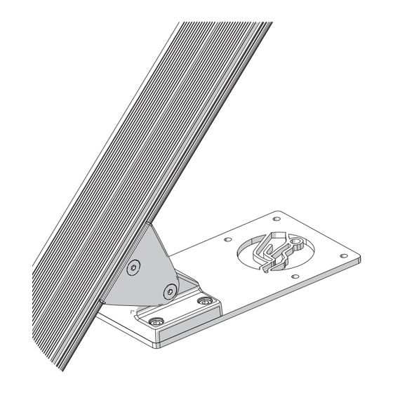
Page 16: Adaptorplate
ZERO INTRUSION ADAPTOR PLATE RIGHT CONFIGURATION LH man NEXT RH man LH pow PAGE RH pow M6x40 M6x12 ONE INSTALL ONLY LEFT CONFIGURATION LEFT CONFIGURATION DO NOT INSTALL THE STANDARD ADAPTORPLATE 5 mm 14 Nm M6x40 124 Lb-In INSTALLATION MANUAL... - Page 17 EXPLANATION [18]Remove the tilt chassis components from the boxes. LEFT CONFIGURATION: [19_L]Assemble the adaptor set (adaptor plates/bolts/washers/bracket). Install the large Zero intrusion adaptorplate in stead of the standard adaptorplate. [20_L]Secure the adaptor plates, washers and bracket to the bottom of the power pack (14 Nm | 124 Lb-In){B}. Adjust the adaptor plate until it is horizontal {A}.
- Page 18 ZERO INTRUSION CHASSIS RIGHT CONFIGURATION DO NOT INSTALL THE REGULIER ADAPTORPLATE 5 mm 14 Nm 124 Lb-In M6x40 5 mm M6x12 INSTALLATION MANUAL...
- Page 19 EXPLANATION RIGHT CONFIGURATION: [19_R]Assemble the adaptor set (adaptor plates/bolts/washers/bracket). Install the large Zero intrusion adaptorplate in stead of the standard adaptorplate. [20_R]Secure the adaptor plates, washers and bracket to the bottom of the power pack (14 Nm | 124 Lb-In){B}. Adjust the adaptor plate until it is horizontal {A}.
-
Page 20: Fasten The Bolts
ZERO INTRUSION FASTEN THE BOLTS 14 Nm 124 Lb-In 5 mm INSTALLATION MANUAL... - Page 21 EXPLANATION [23]Finally tighten the 4 bolts securely (14 Nm | 124 Lb-In). [23]Draai vervolgens de 4 bouten stevig vast (14 Nm). [23]Finalmente, apriete los 4 pernos firmemente (14 Nm). [23]Ziehen Sie die 4 Bolzen schließlich gut fest (14 Nm). [23]Serrez fermement les quatre boulons (14 Nm). [23]Infine, serrare i quattro bulloni (14 Nm).
-
Page 22: Seat Loom
ZERO INTRUSION SEAT LOOM Ph 3 Follow the normal installation steps until fig. 6.8{manual} or 7.11{powered} of the installation manual. Continue the normal installation steps from fig. 6.9{manual} or 7.12{powered} until fig. 8.1 of the installation manual. INSTALLATION MANUAL... - Page 23 EXPLANATION [24]Drill two self drilling screws through the designated holes into the second adaptor plate. Follow the normal installation steps until fig. 6.8{manual} or 7.11{powered} of the installation manual. [25]Connect the seat cable to the PCB cable {A8}{A}.Connect the seat cable to the swivel cable {A9}{B}. [26]Tuck away all of the cables and connectors in the tilt chassis.
-
Page 24: Cover
CHASSIS COVER 3 mm Only adaptor side Continue the normal installation steps from fig. 8.1 until fig. 8.7 of the installation manual. INSTALLATION MANUAL... - Page 25 EXPLANATION [28]Position the cutting template on the bottom tilt chassis cover. [29]Drill the 2 holes through the template. [30]Use a Stanley knife to cut through the template. [31]Cut out the appropriate part of the cover. [32]File away the sharp edges. Continue the normal installation steps from fig.
-
Page 26: Track
ZERO INTRUSION TRACK 6,3 x 50 (4x4) 6.3x45(3x) AA20942 Ph 3 6.3x45(3x) INSTALLATION MANUAL... - Page 27 EXPLANATION [33+34]Ride the lift up en down. Check the positon of the lift. [35]Secure the plate of the top bracket in position using screws (for wooden stairs) or rawl plugs/screws (for concrete/stone stairs). [36]Secure the plate of the bottom bracket in position using screws (for wooden stairs) or rawl plugs/screws (for concrete /stone stairs).
- Page 28 ZERO INTRUSION SUPPORTS 4x or 6x 4x or 6x 221 Lb-In 25 Nm 5 mm Continue with the normal installation steps and checks of the installation manual. INSTALLATION MANUAL...
- Page 29 EXPLANATION [38] Fasten the bolts of all the extension plates {25 Nm | 221 Lb-In}. [39]Check the tightness of all the supports under the extension plates. Continue with the normal installation steps and checks of the installation manual. [38] Maak de bouten van alle verlengplaten stevig vast aan de railsteun {25 Nm}. [39]Controleer of alle steunen onder de verlengplaten goed aansluiten.
- Page 30 Concord, ON L4K 4Z9 Deutschland Canada Tel: +49 (0) 571 973398-55 T : 905.850.9003 Fax: +49 (0) 571 973398-56 F : 416.260.0256 data@handicare.com Handicare Montascale Italia Via Chiaviche 17 46020 Pegognaga (MN) Italy Tel: +39 (0) 376 143 3516 handicare-montascale.it INSTALLATION MANUAL INSTALLATIEHANDLEIDING...
Need help?
Do you have a question about the 1100 and is the answer not in the manual?
Questions and answers
Display does not light up - power plug in wall. Trying to charge battery before installing used unit.
The Handicare 1100 stairlift displays error code "2," which indicates that it is not charging. Possible reasons for the display not lighting up when trying to charge the battery include:
1. Faulty Batteries – The batteries may not be delivering enough power, especially if they are old or incompatible replacements.
2. No Charge Current (Code R) – Ensure the power supply is on and functioning correctly.
3. Faulty Power Supply (Code U) – The power supply may be defective and not delivering power to the system.
4. Main Control Board Issues (Codes O or Y) – A memory or software fault in the main control board could prevent the display from lighting up.
5. Loose or Disconnected Wiring – Check all connections to ensure the batteries and power supply are properly connected.
Replacing the batteries with compatible ones and verifying the power supply should help resolve the issue.
This answer is automatically generated