
Subscribe to Our Youtube Channel
Related Manuals for EKO RR-1070-A


Summary of Contents for EKO RR-1070-A
- Page 1 Quick Start Guide Outdoor Reference cell RR-1070-A / RR-1070-M / RR-1070-MT V01/2024...
- Page 2 Outdoor PV reference cell (RR-1070) Introduction RR-1070 is a sophisticated Mono-Crystalline reference cell used in photovoltaic (PV) plants for monitoring performance ratios. Models with Analog (RR-1070) and Digital Output (RR-1070-M/MT (MODBUS 485) providing unique features. Analog Output: This refers to the reference cell having the capability to produce an output signal that varies continuously as the light intensity changes.
- Page 3 Back Module Temperature Sensor (MT version): This sensor measures the temperature at the back of the solar panel. The back module temperature is a more accurate representation of the operating temperature of the solar panel than ambient temperature measurements. This data is vital for assessing the performance of the solar panels under real operating conditions.
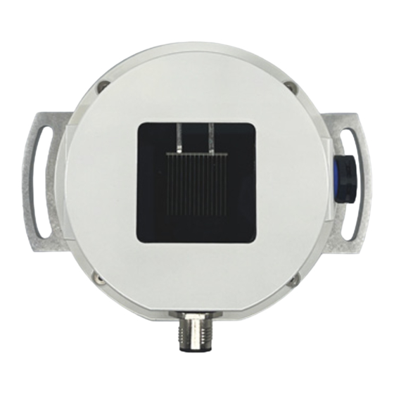
- Page 4 Overview Figure 1: The RR-1070 The RR-1070 is a stable encapsulated Mono-Crystalline silicon solar cell having an area of 20x20mm. The solar cell is calibrated for the AM1.5G spectrum and should be used to monitor the irradiance for PV- applications. The External Quantum Efficiency (EQE) of each device is measured and delivered with the instrument.
- Page 5 Keep Important Documents: o Set aside the calibration certificate that came with the item. Table 1. Box content Item Comment Reference cell RR-1070-A / M / MT Calibration certificate External Quantum Efficiency (EQE) Download file PVConfig Software Document that describes...
-
Page 6: Installation
Installation Setting up a reference cell in a photovoltaic (PV) plant is a crucial step for accurate performance monitoring. The process involves selecting the right location, installing the cell correctly, and integrating it with the monitoring system. Here's a general guide on how to do this: 1. - Page 7 4. Integrate with the PV Monitoring System: Ensure the data from the reference cell is correctly integrated into the PV monitoring system. This might involve configuring software settings, setting up data logging intervals, and ensuring correct data transmission. 5. Configure and Test the System: Once everything is connected, configure the system according to your monitoring requirements.
- Page 8 The RR-1070 has an M12 connector with 5 contacts and is shielded to be used with 5 wire shielded cables. Sensor output wiring for analog model A: Code Brown White Blue Black Gray RR-1070-A Signal + Signal - Digital wiring for MODBUS RTU model M/MT: Code Brown White Blue Black...
-
Page 9: Specifications
Specifications Table 2. RR-1070 series general specifications Measurement Range 0 to 2000W/m2 Cell material Mono crystalline Silicon Cell dimensions 20x20mm Window EVA and PV glass Operating temperature -40 to 80°C Temperature sensor NTC (NTCLE350E4103FHB0) -55°C to 85°C Shunt 500mΩ, 0.2ppm/K Short circuit current (I Approx. - Page 10 Drawings Installation Mono-Crystalline ISO type reference cell (RR-1070)
- Page 11 1. Setup o The installation base or mast should have enough load capacity for the instrument to be mounted. Fix the reference cell securely to the base or mast with bolts and nuts; otherwise, the instrument may drop due to gale or earthquake, which may lead to unexpected accidents. o Make sure the instrument and the cables are installed in a location where they will not get soaked.
-
Page 12: Power Supply
3. Power Supply Make sure to ground the grounding cable on the power supply cable. When grounding is insufficient, it may cause not only measurement error due to noise and electric surge, but also cause electric shock and leakage accidents. Check the voltage and types (AC or DC) of specified power supply before connecting this instrument. - Page 13 Modbus RTU Table A1. Modbus RTU communication protocol (Version from 01/24) Table A2. Modbus RTU data format Table A3. Modbus RTU Default settings Modbus ID (address) Last 2 digits of serial number Baudrate 19200 Parity Even Stopbits Mono-Crystalline ISO type reference cell (RR-1070)
- Page 14 Sensor output voltage Unit: mV External Temperature measured by the temperature external temperature sensor (RR1070-MT only). Note: All other registers can be viewed and adjusted using the pvconfig software. Download from eko-instruments.com product page Mono-Crystalline ISO type reference cell (RR-1070)
-
Page 15: Analog Model
Analog model The analog model (RR1070-A) outputs the irradiance as a voltage reading over the internal shunt. At 1000Wm-2 this reading is about 65mV, the exact value is given on the calibration sheet and can be found on the instrument label. The sensor temperature can be calculated from the NTC resistor value that is mounted on the internal solar cell. - Page 16 PVConfig The RR1070-M and RR1070-MT can be configured using the pvconfig tool. This software can be downloaded for free from the pvblocks.com website. Go to the download section to find pvconfig and use the appropriate installer. It will run on Windows, MacOS and Linux and provides basic support for setting up the device.
- Page 17 Example: Select the COM port assigned to the USB/RS485 adapter and fill in the settings: Figure A2: Communication setting In this case the serial number of the device is 120721, which results in the Modbus address (ID) of 21. Press ‘Connect’ to retrieve all data of the device. Mono-Crystalline ISO type reference cell (RR-1070)
- Page 18 If the connection is successful, all data is shown as can be seen above. By pressing the ‘Read Device Button' button, the information is updated. You can change the calibration value and date. This will be saved into the instrument after pressing the ‘Apply’ button. The Modbus ID and communication parameters can be changed.
- Page 19 Recovery In the case of loss of Modbus ID and/or communication parameters use the following steps to recover. Remove the power from the RR1070-M(T) The first 5 seconds after powerup the instrument is listening to Modbus ID 127 and uses communication parameters: 9600, None, 1 Press the ‘Factory’...
-
Page 20: Warranty
Warranty For warranty terms and conditions, contact EKO or your distributor for further details. EKO guarantees that the product delivered to customer has been verified, checked and tested to ensure that the product meets the appropriate specifications. The product warranty is valid only if the product has been installed and used according to the directives provided in this instruction manual. - Page 21 RoHS Directive 2002/95/EC o EKO Instruments has completed a comprehensive evaluation of its product range to ensure compliance with RoHS Directive 2002/95/EC regarding maximum concentration values for substances. As a result all products are manufactured using raw...
- Page 22 Contact EKO Instruments Europe B.V. Lulofsstraat 55, unit 28 2521 AL, Den Haag The Netherlands Email: Sales-eu@eko-instruments.com Phone: +31703050117 Mono-Crystalline ISO type reference cell (RR-1070)
Need help?
Do you have a question about the RR-1070-A and is the answer not in the manual?
Questions and answers