Table of Contents
Advertisement
Quick Links
Cod.
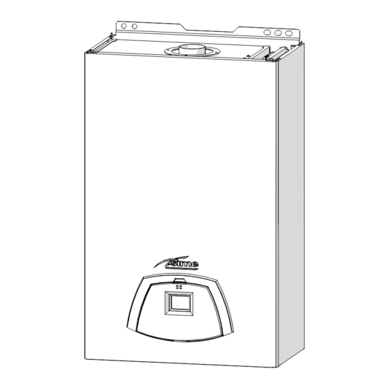
Low temperature wall mounted boiler
EDEA BF R
INSTALLATION AND SERVICING INSTRUCTIONS
NOT TO BE LEFT WITH THE END USER
EN
Gas Safety Certified AS/NZS 5263.1.2
LN: SAI-400434
CAUTION
This product must be installed exclusively by professional-
ly qualified personnel in accordance with the requirements
of the standards AS/NZS 5601, AS/NZS 3500, AS/NZS 3000
To consult the documentation,
(current version) of the local gas, electricity authorities and
visit our website www.sime.it
other relevant legislation.
Fonderie SIME S.p.A.
6333527 - 02/2024 - R1
TRANSLATION OF THE ORIGINAL INSTRUCTIONS
Advertisement
Chapters
Table of Contents

Related Manuals for Sime EDEA BF R


Summary of Contents for Sime EDEA BF R
- Page 1 Cod. Low temperature wall mounted boiler EDEA BF R INSTALLATION AND SERVICING INSTRUCTIONS NOT TO BE LEFT WITH THE END USER Gas Safety Certified AS/NZS 5263.1.2 LN: SAI-400434 CAUTION This product must be installed exclusively by professional- ly qualified personnel in accordance with the requirements...
- Page 2 It must therefore be kept – The appliance must be used as intend- for future reference and must always ed by Sime who is not responsible for accompany the appliance in the event any damage caused to persons, ani-...
- Page 3 RESTRICTIONS IT IS FORBIDDEN IT IS FORBIDDEN – To allow children under the age of 8 to – To expose the boiler to atmospheric use the appliance. The appliance can agents. These boilers can also be in- be used by children no younger than stalled in partially covered areas, as 8 years old, by people with physical per EN 15502, with a maximum ambi-...
- Page 4 Dear Customer, MANUAL STRUCTURE Thank you for purchasing a Sime Edea BF 30 R boiler, a lat- This manual is organized as follows. est-generation low-temperature modulating appliance, with all the technical and performance features to satisfy your heating needs, in maximum safety and with low running costs.
-
Page 5: Table Of Contents
DESCRIPTION OF THE APPLIANCE TABLE OF CONTENTS Technical features ....... 9 DESCRIPTION OF THE APPLIANCE Main water circuit . -
Page 6: Description Of The Appliance
The Edea BF 30 R boilers can be identified by means of: Edea BF 30 R boilers which Sime has produced for heating ONLY. The model this is located on the outside of the packag- Packaging label:... -
Page 7: Structure
Structure 1.4.1 Edea BF 30 Ri Fan (V) System relief valve (VS) Dual sensor (thermal safety/ Boiler drain delivery) System pump (PI) Combustion chamber Automatic bleed valve Ignition/detection electrode Burner (BR) (EAR) Primary heat exchanger Control panel System expansion vessel (VE) Gas valve Flue gas pressure switch Water pressure transducer... -
Page 8: Edea Bf 30 Re
1.4.2 Edea BF 30 Re Fan (V) Water pressure transducer Dual sensor (thermal safety/ (TPAC) delivery) Automatic bleed valve Combustion chamber Burner (BR) Ignition/detection electrode Primary heat exchanger Expansion vessel (VE) (EAR) Control panel Smoke outlet (CSFU) Gas solenoid valve (EVG) System relief valve (VS) Boiler drain System pump (PI) -
Page 9: Technical Features
Technical features Edea BF DESCRIPTION 30 Ri 30 Re CERTIFICATIONS Country of intended installation Fuel NATURAL GAS / UNIVERSAL LPG SAI GLOBAL number SAI-400434 Class NO 5 (< 70 mg/kWh) HEATING PERFORMANCE HEAT INPUT Nominal MJ/h Minimum MJ/h 60.0 HEAT OUTPUT Nominal (80-60°C) 28.1 Minimum (80-60°C) -
Page 10: Main Water Circuit
Main water circuit 0°C 1°C 2°C 3°C 4°C 5°C 6°C 7°C 8°C 9°C 0°C 27279 26135 25044 24004 23014 22069 21168 20309 19489 18706 10°C 17959 17245 16563 15912 15289 14694 14126 13582 13062 12565 20°C 12090 11634 11199 10781 10382 9999 9633... -
Page 11: Control Panel
DISPLAY 1.10 Control panel . The symbol for Summer mode is displayed. “SUMMER” If the symbols are flashing, this indicates that the chimney sweep function is active. “WINTER” . This symbol appears when the boiler is oper- ating in Winter mode. If no operating modes have been enabled both symbols will be off. -
Page 12: Wiring Diagram
1.11 Wiring diagram SAUX TPAC 3 2 1 CN12 CN13 CN15 CN14 CN11 Line Water pressure transducer Blue TPAC Neutral Air thermostat Brown TA-TA2 Fuse (3.15AT - 250V) Expansion card Black Ignition transformer External sensor Green System pump Auxiliary sensor Orange SAUX Remote control (instead of... - Page 13 INSTALLATION AND SERVICING INSTRUCTIONS TABLE OF CONTENTS INSTALLATION MAINTENANCE Receiving the product ......14 Adjustments.
-
Page 14: Installation
INSTALLATION CAUTION Edea BF Description The appliance must only be installed by the Sime Tech- 30 Ri 30 Re nical Service or by qualified professionals who MUST W (mm) suitable protective safety equipment. wear D (mm) 250 (*) 248 (*) -
Page 15: New Installation Or Installation Of A Replacement
Cleaning the system APPROXIMATE MINIMUM DISTANCES Before installing the appliance on a newly constructed system ≥ 5 or replacing a heat generator on an existing system, it is im- portant that the system is thoroughly cleaned to remove sludge, slag, dirt, residue etc. Before removing an old heat generator from an existing system, ≥... -
Page 16: Boiler Installation
Edea BF 30 Re Boiler installation The boilers Edea BF 30 R they leave the factory with the sheet metal template for mounting them on a solid wall. For installation: – remove the coaxial duct and the casing (only for Edea BF 30 Re ) –... -
Page 17: Connecting The Flue
2.11 Connecting the flue 2.11.1 Flue Terminal Positions Door Fig. 17 Edea BF 30 R DESCRIPTION Min. Clearance (mm) Flue terminal Mechanical air inlet Gas meter Electricity meter of fuse box Shaded area indicates prohibited area Below eaves, balconies and other projections (Appliances over 50MJ/h) From the ground, above a balcony or other surface From a return wall or external corner From a gas meter... -
Page 18: Smoke Outlet And Combustion Air Inlet
Edea BF 30 R Coaxial accessories flue ducts and combustion air inlet ducts. These ducts are con- sidered an integral part of the boiler and are provided by Sime Code Description as an accessory kit, to be ordered separately from the appliance Ø... -
Page 19: 2.12.2 Edea Bf 30 Re
External sensor kit (ß=3435, NTC 10KOhm at 25°C) 8094101 Remote control HOME (open therm) 8092280 Remote control HOME PLUS (open therm) 8092281 Remote control Wi-Fi SIME SMART (open therm) 8118900 Fig. 20 CAUTION The maintenance interventions described must ONLY KEY: be carried out the professionally qualified personnel. - Page 20 To facilitate introduction of the connection wires of the optional – bring the control panel (4) to the original position and secure components into the boiler: it with the screws (3) which were removed previously – remove the coaxial fume exhaust duct of the Edea BF 30 Re –...
-
Page 21: 2.13.1 External Temperature Sensor
2.13.1 External temperature sensor 2.13.2 Chrono-thermostat or Air Thermostat The boiler is prearranged for connection to an external air tem- The electrical connection of the chrono-thermostat or air ther- perature sensor and can operate with a sliding temperature. mostat has already been described. When fitting the component This means that the delivery temperature sent to the boiler can in the room where the readings are to be taken, follow the in- vary on the basis of the external temperature depending on the... -
Page 22: Refilling Or Emptying
MULTI ZONE system - with pump, air thermostat and external Heating circuit: sensor. – open the isolation and air bleeding valves in the highest points of the system – loosen the automatic bleed valve (3) – open the isolation valves of the heating circuit (if present) –... -
Page 23: 2.14.2 Emptying Operations
2.14.2 EMPTYING operations Boiler: – loosen the automatic bleed valve (3) – close the heating circuit isolation valves (prearranged in in- stallation) – check that the filling valve is closed – connect a rubber hose to the boiler drain valve (7) and open it –... -
Page 24: Commissioning
COMMISSIONING Preliminary operations – press the button once for at least 1 second to select "WINTER mode" . The value of the heating water tempera- ture detected at that moment will appear on the display WARNING – Should it be necessary to access the areas in the bottom part of the appliance, make sure that the system components and pipes are not hot (risk of burning). -
Page 25: List Of Parameters
– press the button > to scroll up the list of parameters and then – press the > key to increase the value, or the < key to decrease < to scroll down the list the value – to confirm the value, press the key. - Page 26 Type Description Range Step Default 0 = not used 1 = remote alarm NO 2 = remote alarm NC 3 = zone valve External relay 2 function 4 = automatic filling 5 = external request 6 = recirculation pump 7 = zone valve with OT 8 = relaunch pump 0 = according to TA Auxiliary TA function...
-
Page 27: Display Of Operating Data And Counters
TABLE OF INFORMATION DISPLAYED Display of operating data and counters Type Description Range Step Once the boiler is operating a qualified technician can view the SW version operating data and the counters as follows:> External – from the operating screen in the "WINTER" mode temperature - 9 .. -
Page 28: Checks And Adjustments
– close the gas valve Checks and adjustments – loosen the "nozzle pressure" point (6) and the screw of the "supply pressure" point (7) and connect each one to a pres- 3.6.1 Chimney sweeper function sure gauge The chimney sweeper function is used by the qualified mainte- nance technician to check the gas pressure at the nozzles, de- tect the combustion parameters and to measure the combus- tion efficiency required by legislation in force. -
Page 29: Adjusting Gas Pressure At The Nozzles
Adjusting maximum gas pressure: – press the button > once again to make the boiler operate at – turn dials and set the HEATING SET to maximum maximum power. If the gas pressure values are correct it is – press and hold down the buttons <... -
Page 30: Gas Conversion
Gas conversion models can be converted from operation with NAT- Edea BF 30 R URAL GAS to operation with UNIVERSAL LPG by installing the "Nozzle kit for G30/G31", code 5144726, which must be ordered separately from the boiler.. CAUTION The maintenance interventions described must ONLY be carried out the professionally qualified personnel. -
Page 31: Automatic Calibration Procedure
– tighten the counter-nut (10) and the swivel joint (9) and posi- Automatic calibration procedure tion the gasket – refit the electrode (8) putting its end IN THE MIDDLE of the CAUTION burner element (*) This procedure and the procedures relating to " Gas –... - Page 32 – press the > button to scroll the parameters until you reach – press and hold the button > to set the value at "49" parameter "03" – once the required value has been reached, press the button – once the required parameter has been reached, press the to confirm button to confirm and access the set value which will...
- Page 33 Adjusting maximum gas pressure: – disconnect the pressure gauges, carefully close the pressure – turn dials and set the HEATING SET to maximum points (6) and (7), put the control panel back to the original – press and hold down the buttons <...
-
Page 34: Maintenance
MAINTENANCE Adjustments Cleaning the inside of the appliance For the appliance to operate correctly and efficiently it is recom- 4.3.1 Cleaning the heat exchanger mended that the User calls upon the services of a Professionally Qualified Technician to carry out BI-ANNUAL maintenance. To clean the heat exchanger: –... -
Page 35: Cleaning The Burner
4.3.4 Final operations – remove the four screws (3) and remove the front panel (4) from the combustion chamber (6) working carefully so as not After having cleaned the heat exchanger and the burner: to damage the gasket or the panel insulation –... -
Page 36: Unscheduled Maintenance
Unscheduled maintenance Type Fault Solution If replacing the electronic board , the user MUST set the parame- - Check the integrity of the electrode and check ters as indicated in the table and in the sequence shown. Fault in the flame that it is not grounded Setting for Edea BF detection circuit... -
Page 37: Maintenance Request
4.6.1 Maintenance request Type Fault Solution When it is time to perform maintenance on the boiler, the EV2 SGV current upper - Check gas valve and symbol shows on the display. limit error board EV2 SGV current lower - Check gas valve and limit error board Fault on the valve control... -
Page 38: Commissioning Boiler Checklist
COMMISSIONING BOILER CHECKLIST A suggested method of commissioning the boiler; the actual method can vary according to the boiler make, type and installation. The boiler must always be installed and commissioned by an approved gas technician. The installer certifies that this Boiler has been in- stalled to the manufacturer's instructions, has been filled, commissioned and is ready for use. -
Page 39: Exploded Views
EXPLODED VIEWS Edea BF 30 Ri... - Page 40 Edea BF 30 Re...
- Page 41 - Edea BF 30 Re Edea BF 30 Ri...
- Page 42 - Edea BF 30 Re Edea BF 30 Ri...
- Page 43 Edea BF Edea BF Recommended Recommended Pos. Code Description Pos. Code Description spare parts spare parts 6264561 Frame 6120560 Pump nipple 3/4" Spring clip for Sealed chamber rear 6226644 6317612 rotating connec panel ORing Gasket for sealed 6226475 6229838 diam.18,64x3,53 chamber Modulating circulating Rectang.
-
Page 44: Removing Components
REMOVING COMPONENTS CAUTION Remove panels – The maintenance interventions described must ONLY be carried out the professionally qualified 7.2.1 Front panel personnel who MUST wear suitable protective safety To access the internal parts of the boiler: equipment. – Make sure that the system components and pipes CAUTION are not hot (risk of burning). -
Page 45: Side Panels
7.2.2 Side panels 7.2.4 Combustion chamber panel – unscrew the screws (3) – remove the four screws (3) and remove the front panel (4) – pull the side panel (4) outwards to release it from the top from the combustion chamber (6) working carefully so as not to damage the gasket or the panel insulation Fig. -
Page 46: Dual Sensor (Thermal Safety/Discharge)
Dual sensor (thermal safety/discharge) Remove electronic board – Remove front panel (see "Remove panels" on page 44) – Remove front panel (see "Remove panels" on page 44) – disconnect the connector (1) – move the control panel (A) into a horizontal position (see "Ro- tate control panel"... -
Page 47: Remove/Replace Fan
Remove/replace fan Removal/replacement of flue gas pressure switch – Remove front panel (see "Remove panels" on page 44) – Remove front panel (see "Remove panels" on page 44) – Remove the front panel of the sealed chamber (see "Sealed chamber panel" on page 45) –... -
Page 48: Remove/Replace Ignition Electrode And Nozzles
– unscrew the swivel joints (2) and the screws (3) Remove/replace ignition electrode and nozzles – Remove front panel (see "Remove panels" on page 44) – Remove the front panel of the sealed chamber (see "Sealed chamber panel" on page 45) –... -
Page 49: Remove/Replace The Expansion Vessel
7.10 Remove/replace the expansion vessel 7.11 Remove/replace system pump – Shut-off the valves to the system and empty the boiler CAUTION – remove the front panel (see "Remove panels" on page 44) – lift the connector (1) using a screwdriver (2) When disassembling, some residual water may leak. - Page 52 Fonderie Sime S.p.A - Via Garbo, 27 - 37045 Legnago (Vr) Tel. +39 0442 631111 - Fax +39 0442 631292 - www.sime.it...
Need help?
Do you have a question about the EDEA BF R and is the answer not in the manual?
Questions and answers