
Related Manuals for lanry TF1100-DC Series


Summary of Contents for lanry TF1100-DC Series
- Page 1 TF1100-DC/DI Series Dual-channel Transit Time Ultrasonic Flow Meter Clamp-on & Insertion Operation & Maintenance Manual REV 3/2023 Copyright ©Lanry Instruments(shanghai) Co.,Ltd. All rights reserved.
-
Page 2: Table Of Contents
TF1100-EC/EI transit-time ultrasonic heat meter manual CONTENTS PART-1 INTRODUCTION .........................1 1.1 GENERAL ............................1 1.2 PRINCIPLE OF MEASUREMENT ....................1 1.3 APPLICATIONS ..........................2 1.4 FEATURES ............................3 1.5 SPECIFICATIONS ..........................4 1.6 PARTS IDENTIFICATION ........................5 PART-2 TRANSDUCER INSTALLATION ....................6 2.1 GENERAL ............................ - Page 3 TF1100-EC/EI transit-time ultrasonic heat meter manual 7.7 HOW TO USE THE 4~20M A OUTPUT ..................36 7.8 HOW TO USE THE RELAY OUTPUT .....................37 7.9 HOW TO USE PULSE OUTPUT ......................37 7.10 HOW TO SET THE DATE AND TIMER ..................37 7.11 ON/OFF NET TOTALIZER ......................38 7.12 UNITS OPTIONS ..........................
-
Page 4: Part-1 Introduction
TF1100-EC/EI Manual PART-1 INTRODUCTION 1.1 GENERAL Dual-channel wall-mounted transit-time ultrasonic flow meters works on transit-time principle. It includes TF1100-DC clamp-on type and TF1100-DI insertion type. They are used for liquid flow measurement in fully filled pipe. Two types of transducers are sufficient to cover the most common pipe diameter ranges and materials. -
Page 5: Applications
TF1100-EC/EI Manual Kdt TL Where: Liquid velocity Constant Difference in time of flight Average Transit Time When measuring temperature, the two temperature sensors of Pt1000 clamp on the pipeline or insert in the pipe, and get two temperature values. The value of energy is indicated / measured based on the following mathematical model: Where: Q –... -
Page 6: Features
TF1100-EC/EI Manual 1.4 FEATURES Advanced Digital Signal Processor technology and the MultiPulse transducer technology. Dual channels ultrasonic transit-time sensors for high accuracy 0.5%. Wide liquid temperature range:-35°C-200°C. Thermal energy measure capability can be optional. Dynamic zero. ... -
Page 7: Specifications
TF1100-EC/EI Manual 1.5 SPECIFICATIONS Transmitter: Principle Ultrasonic transit-time difference correlation principle Channels Velocity range 0.01 to 15 m/s, bi-directional Resolution 0.1mm/s Repeatability 0.15% of reading Accuracy ±0.5% of reading at rates >0.3 m/s);±0.003 m/s of reading at rates<0.3 m/s Response time 0.5s Sensitivity 0.003m/s... -
Page 8: Parts Identification
TF1100-EC/EI Manual 1.6 PARTS IDENTIFICATION Transmitter Clamp-on transducer Insertion transducer S-S Belt PT1000 clamp-on PT1000 insertion Couplant Drill tools Ball valve base... -
Page 9: Part-2 Transducer Installation
TF1100-EC/EI Manual PART-2 TRANSDUCER INSTALLATION 2.1 GENERAL The transducers that are utilized by the Series TF1100 contain piezoelectric crystals for transmitting and receiving ultrasound signals through walls of liquid piping systems. The transducers are relatively simple and straight-forward to install, but spacing and alignment of the transducers is critical to the system's accuracy and performance. -
Page 10: Transducer Spacing
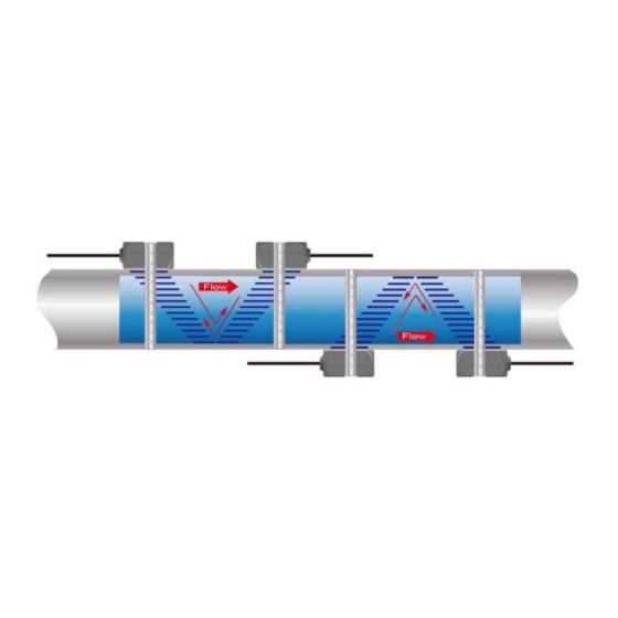
TF1100-EC/EI Manual Upstream Downstream Piping configuration Dimension Dimension And transducer Pipe Diameters ( *) Pipe Diameters(**) position ( take a pair of sensors for example) Table 2.1 Straight Pipe Requirement 2.3 TRANSDUCER SPACING TF1100 transducers are clamped on the outside of a closed pipe at a specific distance from each other. - Page 11 TF1100-EC/EI Manual Transducer Mounting Modes Z method V method The TF1100 system calculates proper transducer spacing by utilizing piping and liquid information entered by the user. The following information is required before programming the instrument. Note that much of the data relating to material sound speed, viscosity and specific gravity are...
-
Page 12: Transducer Mounting
TF1100-EC/EI Manual preprogrammed into the TF1100 flow meter. This data only needs to be modified if it is known that a particular liquid data varies from the reference value. Refer to Part 3 of this manual for instructions on entering configuration data into the TF1100 flow meter via the meter keypad. - Page 13 TF1100-EC/EI Manual Pipe Preparation Before the transducers are mounted onto the pipe surface, four areas slightly larger than the flat surface of the transducer heads must be cleaned of all rust, scale and moisture. For pipes with rough surfaces, such as ductile iron pipe, it is recommended that the pipe surface be ground flat.
- Page 14 TF1100-EC/EI Manual Figure 2.3 Transducer position V-Mount is the STD installation method, it is convenient and accurate, reflective type (transducers mouthed on one side of the pipe) of installation used primarily on pipe size in the (50mm~400mm) internal diameter range attention transducer designed parallel on the centre line of installing the pipeline.
- Page 15 TF1100-EC/EI Manual 3. Crease the paper at the fold line. Mark the crease. Place a mark on the pipe where one of the transducers will be located. See Figure 2.1 for acceptable radial orientations. Wrap the template back around the pipe, placing the beginning of the paper and one corner in the location of the mark.
-
Page 16: Transducer Mounting Inspection And Couplant Application
TF1100-EC/EI Manual RSSI of between 60 and 95 percent is acceptable. On certain pipes, a slight twist to the transducer may cause signal strength to rise to acceptable levels. 7. Secure the transducer with a stainless steel strap or other. 8. -
Page 17: Part-3 Transmitter Installation Connection And Operation Instructions
TF1100-EC/EI Manual PART-3 TRANSMITTER INSTALLATION CONNECTION AND OPERATION INSTRUCTIONS 3.1 TRANSMITTER INSTALLATION After unpacking, it is recommended to save the shipping carton and packing materials in case the instrument is stored or re-shipped. Inspect the equipment and carton for damage. If there is evidence of shipping damage, notify the carrier immediately. -
Page 18: Transducer Connections
TF1100-EC/EI Manual Figure 3.1 Mechanical Dimensions 3.2 TRANSDUCER CONNECTIONS To access terminal strips for electronic connectors, loosen the two screws in the enclosure door and open the door. Guide the transducer terminations through the transmitter conduit hole located in the bottom-center of the enclosure. -
Page 19: Transmitter Power And Output Connections
TF1100-EC/EI Manual Figure 3.2 NOTE: The transducer cable carries low level high frequency signals. In general, it is not recommended to add additional cable to the cable supplied with the transducers. If additional cable is required, contact the factory to arrange an exchange for a transducer with the appropriate length of cable. -
Page 20: Keypad Configuration
TF1100-EC/EI Manual Figure 3.3 Pulse Wires Connection 4, Relay “+, -”, only For Totalizer Output Once the transmitter is powered on, the “RELAY +, -” output is normally Open state. When the relay is used for totalizer output, connect terminal “RELAY + -“, select the corresponding totalizer in Menu, and setup the minimum display totalizer increments. - Page 21 TF1100-EC/EI Manual Follow these guidelines when using TF1100 keypad: 0 ~ 9 and . to input numbers and decimal. CLR to backspace or delete characters to the left. The ARROW keys 8∧ and 2 ∨ To return to the last menu or to open the next menu, are used to scroll through menu configuration parameters;...
-
Page 22: Pipe Parameter Entry Shortcuts
TF1100-EC/EI Manual 3.5 PIPE PARAMETER ENTRY SHORTCUTS The following parameters should be entered for normal measurement: a. Pipe outer diameter b. Pipe wall thickness c. Pipe material d. Liner material parameters (including thickness and sound velocity, if needed) e. Fluid type f. -
Page 23: Part-4 Windows Display Explanations
TF1100-EC/EI Manual PART-4 WINDOWS DISPLAY EXPLANATIONS TF1100 Window Descriptions When reading this section, please refer to the meter menu one by one for easy understanding The quick way to check display window is to press the ESC key and then press ENT key to check initial Settings. - Page 24 TF1100-EC/EI Manual CH1+2 CL Output CL Calibration / CL RSSI Output Checkup Flow Positive, negative, Current Loop Total Window Current net total flow Output Display Flow Loop Display Output Time/ Flow CL Mode Output/Max Velocity Output Outer Diameter Current Output Output Wall Thickness Logger Output...
- Page 25 TF1100-EC/EI Manual Positive total /negative total /net total /flow /Velocity /channel number /RSSI, Q value /time Display positive total flow, negative total flow, net total flow, instantaneous flow and velocity, upstream and downstream signal strength RSSI, signal quality Q value and time. Signal strength is expressed in numbers from 0 to 99.9.
- Page 26 TF1100-EC/EI Manual using ↑ and ↓ keys, you can select the corresponding function and enter ENT for selection or modification. CH 1+2 RSSI=93.0-92.8/95.9-95.6 Q=92.2/93.4 10:36:37 Pipe Parameter Flow Unit Set Totalizer Set Flow Cut-off: 0.00001m/s Flow Scale Factor: 0.90800 Pipe Parameter Menu Outer Diameter/ Wall Thickness /Lining Thickness/ Inner Diameter/ Pipe MAT/Liner MAT./ Kind Of Fluid/ Sensor Type/ Sensor Mounting/ Zero Adjust/ Damping Set/ Empty Pipe Set/ Measure CHAN Set/ Static Zero Reset/ Liquid Temperature/ Sensor Distance...
- Page 27 TF1100-EC/EI Manual CH 1+2 RSSI=93.0-92.8/95.9-95.6 Q=92.2/93.4 10:36:58 Damping Set : 10 Empty Pipe Set: 60 Measure CHAN Set: CH1 Static Zero Reset: Off Liquid Temperature: 20.0 C CH 1+2 RSSI=93.0-92.8/95.9-95.6 Q=92.2/93.4 10:36:58 Sensor Distance: 82.76mm Outer Diameter This menu for entering/changing the outside (outer) diameter of the pipe line. 0 to 6000 mm is the allowed range of the value.
- Page 28 If the user selects 7 user, sensor parameters including: Angle of acoustic wedge, acoustic wedge speed, ultrasonic delay time, distance between the center of the acoustic beam and the edge of the sensor must be entered. Please contact Lanry Instruments for specific usage method. Plug-in Type B is for standard Insertion sensor 65-6000mm.
- Page 29 TF1100-EC/EI Manual Zero Adjust Automatic zero/ manual zero/ static zero/ factory zero Automatic zero is usually chosen. Damping Set Flow rate Damping for displaying a stable read. The input range is 0 to 99. 0 means no damping and 99 means maximum damping. Damping acts as a smooth display of data.
- Page 30 TF1100-EC/EI Manual Users need mount sensors exactly according to the spacing distance value after users input correct parameter setting. This data is automatically calculate by the flow meter after the user enters the all pipeline parameters. Flow Unit Set This window displays Settings for flow unit, for flow rate unit, totalizer flow unit and tolalizer factor.
- Page 31 TF1100-EC/EI Manual Turn on or turn off the NET Totalizer, Positive Totalizer, Negative Totalizer. Positive Totalizer This menu is used to turn on or turn off the positive totalizer, the flowmeter positive totalizer accumulates when it is "ON". When it is “Off”, the positive totalizer will not change.
- Page 32 TF1100-EC/EI Manual Factory default is KWh. Positive Totalizer ( Energy ) This menu is used to turn on or turn off the energy positive totalizer, the flowmeter energy positive totalizer accumulates when it is "ON". When it is “Off”, the energy positive totalizer will not change.
- Page 33 TF1100-EC/EI Manual Calibrate the output temperature. Temp Cut-off Low temperature difference cutoff. SHC is short of specific heat capacity. The meter default calculate the thermal enthalpy as the water of a certain temperature automatically. If the measure fluid is not water, user need to manually enter the fluid specific heat capacity in the menu SHC.
- Page 34 TF1100-EC/EI Manual 20mA . At the same time, use a precision ammeter to check if the output data correct. If the allowable error is exceeded, the current loop needs to be re-calibrated. Current Loop Output and CL mode 4-20mA is the most common output mode. Min Output/Max Output Min Output is used to set the minimum flow value of 4mA or 0mA.
-
Page 35: Part-5 Energy Function
TF1100-EC/EI Manual CH 1+2 RSSI=93.0-92.8/95.9-95.6 Q=92.2/93.4 10:38:49 Net Energy: 16000 Pos Energy: 16000 Neg Energy: 0.000 Curr NRG : 229.693 T1/T2 32.40/22.20 CH 1+2 RSSI=82.2-82.3/82.1-82.2 Q=72.6/75 10:38:49 Transit-Time : 229.75 us Reynolds : CH1 TX-Time Rate: 99.26 CH2 TX-Time Rate: 100.98 CH 1+2 RSSI=82.2-82.3/82.1-82.2 Q=72.6/75 10:38:49... -
Page 36: Wiring Connection
TF1100-EC/EI Manual 5.2 WIRING CONNECTION The fluid temperature is obtained by an external input Pt1000 platinum resistance temperature sensor signal from outside. When calculating energy, T1 connects to inlet sensor and T2 to outlet sensor. 5.3 ENERGY CALCULATION There are two methods to calculate energy: Method 1) :... -
Page 37: Part-6 Temperature Sensor Installation
TF1100-EC/EI Manual PART-6 TEMPERATURE SENSOR INSTALLATION 6.1 PT1000 TEMPERATURE SENSOR TF1100 heat meter utilizes two PT1000 temperature sensors, and the temperature sensors are matching. Temperature sensor cable is provided by manufacturer, and the standard length is 10m. For measurement accuracy, test security, convenient maintenance, and not affect equipment operation and production operation, we should pay attention to the following before installation: 1. -
Page 38: Part-7 How To Use Menu Functions
TF1100-EC/EI Manual Drill a suitable hole on pipe directly, plug in the insertion temperature sensor, adjust the insertion depth, and then fix it. Note: The cables of two temperature sensor must be the same length. PART-7 HOW TO USE MENU FUNCTIONS 7.1 HOW TO JUDGE THE LIQUID FLOWING DIRECTION Make sure that the instrument works properly Check the flow rate for the indication. -
Page 39: How To Use The Low Flow-Cutoff Function
TF1100-EC/EI Manual 7.4 HOW TO USE THE LOW FLOW-CUTOFF FUNCTION The number displayed in menu Flow Cut-off is called the low flow cutoff value or zero cutoff value. The flow meter will replace these flow rate values that are absolutely less than the low-cutoff value with ‘0’. -
Page 40: How To Use The Relay Output
TF1100-EC/EI Manual programmable and configurable with multiple output modules. Select in Window Current Loop Output. Calibrating and testing the current loop 4mA,8mA,12mA,16mA, and 20mA are performed in the Window. Complete the steps as follows: Press Menu, move ∧ or ∨ to display “0mA”, “4mA”, “8mA”, “16mA”, “20mA”... -
Page 41: On/Off Net Totalizer
TF1100-EC/EI Manual 7.11 ON/OFF NET TOTALIZER Window Totalizer Set is available to turn totalizer on and off. 7.12 UNITS OPTIONS Measurement units options, Metric or English, select Flow Unit Set, Press ESC and then ENTER, and scroll the ∧or ∨ to select units; 7.13 LCD BACKLIT OPT IONS Adjustment the backlighting in window , press ENTER, then use ∧or ∨... - Page 42 TF1100-EC/EI Manual installation. The measurement calculations in the flow meter are based upon these two parameters. Therefore, when “Delta Time” fluctuates widely, the flow and velocities fluctuate accordingly. This means that the signal quality detected is too poor. It may be the resulted of poor pipe-installation conditions, inadequate transducer installation or incorrect parameter input.
-
Page 43: Part-8 Frequently Asked Questions And Answers
TF1100-EC/EI Manual PART-8 FREQUENTLY ASKED QUESTIONS AND ANSWERS Q: New pipe, high quality material, and all installation requirements met: why still no signal detected? A: Check pipe parameter settings, installation method and wiring connections. Confirm if the coupling compound is applied adequately, the pipe is full of liquid, transducer spacing agrees with the screen readings and the transducers are installed in the right direction. -
Page 44: Part-9 Warranty And Service
TF1100-EC/EI Manual PART-9 WARRANTY AND SERVICE 9.1 WARRANTY The manufacturer provides one year warranty on all products, free of charge, but the users should be responsible for the one-way transportation fee from the customer to the factory. 9.2 SERVICE The manufacturer provides instrument installation for our customers, and the charges will be made according the cost. -
Page 45: Appendix 1 Insertion Transducer Installation
TF1100-EC/EI Manual APPENDIX 1 INSERTION TRANSDUCER INSTALLATION Overview Insertion transducers can be installed into metal pipelines via an isolation ball valve (installation into pipelines of plastic or other materials may require an optional coupling; If the pipe material is cement, please consult factory to use special lengthen insertion transducer, furthermore, use special cement borer). - Page 46 TF1100-EC/EI Manual By positioning paper, or positioning ropes, first identified point A and then confirmed C points (A and C into 180° symmetric), extended C level again, determined to point B, L = BC Step by step shown as below Fig.2 – 6 Fig.2 Prepare a rectangular paper or substitutes.
-
Page 47: C, Drilling Holes
TF1100-EC/EI Manual C, DRILLING HOLES After removing the auxiliary paper, draw a locating point and use it as the center to drill a hole of 19mm. Then, weld the transducer-mounting base vertically and install the transducer (Figure 7). Note that the inside central point of the transducer (on the other side of the cable connector) must coincide with the position point marked in Fig. -
Page 48: D, Mounting The Transducers
TF1100-EC/EI Manual Figure 9 Drilling hole Diagram After Welding the Ball Valve Base, mount the Ball Valve on base, note use PTFE belt for sealing. Connecting the locking ring of borer to the thread of Ball Valve, tightening, open the Ball Valve, pushing the Borer Pole to outside of pipeline, connecting the 500W Electric Drill to the Borer Pole, tightening, power on, begin to drill hole. -
Page 49: E, Transducer Wiring
TF1100-EC/EI Manual L=A-B (Let C=0) In this formula: L---Mounting height (mm) A--Transducer length (mm) B---Pipe wall thickness (mm) As shown Fig.11 right, the cable holes of two transducers must be in same direction. Important: For horizontal pipelines, transducers must be fixed on the sides of the pipe (i.e. at the 3 and 9 o’clock position of the pipe) to prevent signal attenuation caused by sediment on the bottom of the pipe or air bubbles and air pockets in the top of the pipe. -
Page 50: Appendix 2 Modbus-Rtu Communications Protocol
TF1100-EC/EI Manual APPENDIX 2 MODBUS-RTU COMMUNICATIONS PROTOCOL TF1100-DC&DI series ultrasonic flowmeter default Modbus output Modbus-RTU protocol. The “D+” terminal is connected to RS485 “A”, and “D-” terminal is connected to RS485 “B”. When use Modbus-RTU protocol, please refer to the following steps: a. - Page 51 TF1100-EC/EI Manual Message Address 1 byte Function Code 1 byte Data Address 2 bytes Register Count 2 bytes 2 bytes Response Address 1 byte Function Code 1 byte Byte Count 1 byte Data Payload N bytes 2 bytes *Byte count = 2*Register Count Write Single Register is used to configure instrument settings.
- Page 52 TF1100-EC/EI Manual The below list of parameters will all be located in the holding registers. Register Size Mode Data Type Description Address (byte) float Velocity float Flow double Net Total double Pos Total double Neg Total float T1 Input Value float T2 Input Value Instant Energy...
- Page 53 TF1100-EC/EI Manual Register Size Mode Data Type Description Address (byte) float Outer Diameter(mm) float Wall Thickness(mm) float Lining Thickness(mm) Pipe MAT float User-defined pipe sound speed(m/s) Liner MAT float User-defined liner sound speed(m/s) Kind of Fluid float User-defined liquid sound speed(m/s) Sensor Type User-defined sensor angle float...
- Page 54 TF1100-EC/EI Manual Register Size Mode/ Data Type Description Address (byte) Access Modbus address Baudrate Set Parity Set Relay output Relay Type Relay Flow Unit Relay Energy Unit Pulse Output Pulse Type Pulse Flow Unit Pulse Energy Unit Current Loop Output CL Calibration 4ma Checkup 20maCheckup...
-
Page 55: Appendix 3 Data Logger
TF1100-EC/EI Manual Register Size Mode Data Type Description Address (byte) (Electronic Serial Number) APPENDIX 3 DATA LOGGER Meter Setting Before Using Data Logger Before using the data logger, please check the following items of meter settings (otherwise, the data logger will not work normally): I. - Page 56 TF1100-EC/EI Manual When opening the “csv” file, the data are shown as below: TF1100-DC/DI Ultrasonic flowmeter can storage: data, time, flow, velocity, net totalizer, positive totalizer, negative totalizer, EFR, E.T, Tin, Tout and T.D.
-
Page 57: Appendix 4 Fuild Characteristic (Sound Speed)
TF1100-EC/EI Manual APPENDIX 4 FUILD CHARACTERISTIC (SOUND SPEED) 1. FLUID PROPERTIES Fluid Specific Gravity Sound Speed delta-v/degree Kinematic Absolute Viscosity viscosity 20 degrees C ft/s m/s/degree C Centistokes Centipoise Acetate, Butyl 1270 4163.9 Acetate, Ethyl 0.901 1085 3559.7 0.489 0.441 Acetate, Methyl 0.934 1211... - Page 58 TF1100-EC/EI Manual Linalool 1400 4590.2 Linseed Oil .925-.939 1770 5803.3 Methanol 0.79 1076 3530.2 2.92 0.695 0.550 Methyl alcohol 0.79 1076 3530.2 2.92 0.695 0.550 Methylene chloride 1.33 1070 3510.5 3.94 0.310 0.411 Methylethyl 1210 3967.2 Ketone Motor Oil (SAE .88-.935 1487 4875.4 20/30)
-
Page 59: Water Sound Speed
TF1100-EC/EI Manual 2. WATER SOUND SPEED Water Sound Speed table ( pressure: 1 bar) Units: Sound Speed: m/s Temperature Sound Temperature Sound Temperature Sound Temperature Sound ℃ Speed ℃ Speed ℃ Speed ℃ Speed 1402.3 1496.6 1542.5 1555.1 1407.3 1499.2 1543.5 1555.0 1412.2... - Page 60 TF1100-EC/EI Manual Lanry Instruments (Shanghai) Co.,Ltd Add: 6 Floor,Block F, Bldg 5,No.2800 Jiuxin Rd., Songjiang District, Shanghai 201612,China Tel:86 21-67801665,67618991 Fax:86 21-67801625 http://www.lanry-flow.com...
Need help?
Do you have a question about the TF1100-DC Series and is the answer not in the manual?
Questions and answers