
Related Manuals for lanry TF1100-EP


Summary of Contents for lanry TF1100-EP
- Page 1 TF1100-EP Transit Time Ultrasonic Flow (Heat) Meter Portable Operation & Maintenance Manual REV 1/2023...
-
Page 2: Table Of Contents
TF1100-EP ultrasonic portable flow (heat) meter manual CONTENTS PART-1 INTRODUCTION .........................1 1.1 GENERAL ............................1 1.2 PRINCIPLE OF MEASUREMENT ....................1 1.3 APPLICATIONS ..........................3 1.4 FEATURES ............................3 1.5 SPECIFICATIONS ..........................4 1.6 PARTS IDENTIFICATION ........................5 PART-2 TRANSDUCER INSTALLATION ....................6 2.1 GENERAL ............................ - Page 3 TF1100-EP ultrasonic portable flow (heat) meter manual 7.9 HOW TO USE PULSE OUTPUT ......................36 7.10 HOW TO SET THE DATE AND TIMER ..................36 7.11 ON/OFF NET TOTALIZER ......................36 7.12 UNITS OPTIONS ..........................36 7.13 LCD BACKLIT OPT IONS ......................36 7.14 USE MENU WINDOWS FOR TRANSDUCER MOUNTING INSPECTION ......36...
-
Page 4: Part-1 Introduction
TF1100-EP ultrasonic portable flow(heat)meter manual PART-1 INTRODUCTION 1.1 GENERAL It is the engineers and technicians' hope to measure the flow on the non-invasive pipeline reliably. Series TF1100 are state-of–the-art universal transit-time ultrasonic flow meters, fit to measure flow of full pipe line, providing a measuring system with unsurpassed accuracy, versatility, ease of installation and dependability. - Page 5 TF1100-EP ultrasonic portable flow(heat)meter manual Difference in time of flight Average Transit Time When measuring temperature, the two temperature sensors of Pt1000 clamp on the pipeline or insert in the pipe, and get two temperature values. The value of energy is indicated / measured based on the following mathematical model: Where: Q –...
-
Page 6: Applications
TF1100-EP ultrasonic portable flow(heat)meter manual 1.3 APPLICATIONS 1. Water, sewage (with low particle content) and sea water 2. Water supply and drainage water 3. Process liquids; Liquors 4. Milk, yoghourt milk 5. Gasoline kerosene diesel oil 6. Power plant 7. The flow patrolling and examining 8. -
Page 7: Specifications
TF1100-EP ultrasonic portable flow(heat)meter manual 1.5 SPECIFICATIONS Specifications: Transmitter Measurement principle Ultrasonic transit-time difference correlation principle Flow velocity range 0.01 to 12 m/s, bi-directional Resolution 0.25mm/s Repeatability 0.2% of reading ±1.0% of reading at rates >0.3 m/s);±0.003 m/s of reading at Accuracy rates<0.3 m/s... -
Page 8: Parts Identification
TF1100-EP ultrasonic portable flow(heat)meter manual 1.6 PARTS IDENTIFICATION Transmitter Standard Transducer PT1000 clamp-on PT1000 insertion Output Cable charging cable S-S Belt Couplant SD card reader TF1100-EP Series... -
Page 9: Part-2 Transducer Installation
TF1100-EP ultrasonic portable flow(heat)meter manual PART-2 TRANSDUCER INSTALLATION 2.1 GENERAL The transducers that are utilized by the Series TF1100 contain piezoelectric crystals for transmitting and receiving ultrasound signals through walls of liquid piping systems. The transducers are relatively simple and straight-forward to install, but spacing and alignment of the transducers is critical to the system's accuracy and performance. -
Page 10: Transducer Spacing
TF1100-EP ultrasonic portable flow(heat)meter manual Upstream Downstream Piping configuration Dimension Dimension And transducer Pipe Diameters ( *) Pipe Diameters(**) position Table 2.1 Straight Pipe Requirement 2.3 TRANSDUCER SPACING TF1100 transducers are clamped on the outside of a closed pipe at a specific distance from each other. - Page 11 TF1100-EP ultrasonic portable flow(heat)meter manual Table 2.2 Transducer Mounting Modes Transducer Pipe Liquid Pipe Size Mount Mode Material Composition Plastic 1-30 in. (20-750 mm) Low TSS; V-Mode Metal 2-24 in. (50-600 mm) non-aerated Plastic > 12 in. (> 300 mm) Low TSS;...
-
Page 12: Transducer Mounting
TF1100-EP ultrasonic portable flow(heat)meter manual manual for instructions on entering configuration data into the TF1100 flow meter via the meter keypad. Transducer mounting configuration. See Table 2.2 1. Pipe Outer Diameter) 2. Pipe wall thickness 3. Pipe material 4. Pipe sound speed 5. - Page 13 TF1100-EP ultrasonic portable flow(heat)meter manual Pipe Preparation Before the transducers are mounted onto the pipe surface, two areas slightly larger than the flat surface of the transducer heads must be cleaned of all rust, scale and moisture. pipes with rough surfaces, such as ductile iron pipe, it is recommended that the pipe surface be ground flat.
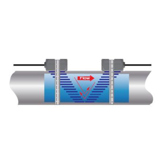
- Page 14 TF1100-EP ultrasonic portable flow(heat)meter manual Figure 2.3 Transducer position V-Mount is the STD installation method, it is convenient and accurate, Reflective type (transducers mouthed on one side of the pipe) of installation used primarily on pipe size in the (50mm~400mm) internal diameter range attention transducer designed parallel on the centre line of installing the pipeline.
- Page 15 TF1100-EP ultrasonic portable flow(heat)meter manual 3. Crease the paper at the fold line. Mark the crease. Place a mark on the pipe where one of the transducers will be located. See Figure 2.1 for acceptable radial orientations. Wrap the template back around the pipe, placing the beginning of the paper and one corner in the location of the mark.
-
Page 16: Transducer Mounting Inspection And Couplant Application
TF1100-EP ultrasonic portable flow(heat)meter manual Figure 2.6 Z-Mode transducer placements 2.5 TRANSDUCER MOUNTING INSPECTION AND COUPLANT APPLICATION 2.5.1 Transducer Mounting Inspection It is very important to use menu operations for TRANSDUCER MOUNTING INSPECTION and Estimation, Refer to 5.16, Use menu windows for Transducer Mounting Inspection. -
Page 17: Part-3 Start Operating Instructions
TF1100-EP ultrasonic portable flow(heat)meter manual PART-3 START OPERATING INSTRUCTIONS 3.1 POWER ON Press the ON key to switch on the instrument and press the OFF to turn off the power. Once the flow meter is switched on, it will run a self diagnostic program, checking first the hardware and then the software integrity. - Page 18 There is no need to specify the transmitting and receiving transducers. (if flow rate display negative, exchange the UP/ DN wiring). For TF1100-EP, pls connect the two transducers with UP1/DN1. UP2/DN2 is only for TF1100-DP dual-channel ultrasonic flowmeter TF1100-DP. T1 and T2 are used for PT1000 temperature sensor wires. T1 is for inlet pipe and T2 is for outlet pipe.
-
Page 19: Keypad Functions
TF1100-EP ultrasonic portable flow(heat)meter manual RS485 connector is for output RS485 Modbus RTU, pls check below wires connection table. Color Description Green RS485 A Blue RS485 B Black 3.3 KEYPAD FUNCTIONS After transducer and connection of appropriate power supply to TF1100, keypad configuration of the instrument can be undertaken. -
Page 20: Pipe Parameter Entry Shortcuts
TF1100-EP ultrasonic portable flow(heat)meter manual The ESC key is used to exit the current screen; The ENT key is confirm key, it is used to "confirm" that a number or selection has been entered. Another function is to enter the "Modify" state before entering parameters. -
Page 21: Part-4 Windows Display Explanations
TF1100-EP ultrasonic portable flow(heat)meter manual Zero Reset,Liquid Temperature as default to factory Settings. 10.Press the ∨ key to check menu Sensor Distance, accurately install the transducer according to the displayed transducer mounting spacing and the selected mounting method (Refer to Installing the Transducers in Part 2). - Page 22 TF1100-EP ultrasonic portable flow(heat)meter manual Main menu window CL Output CL Calibration / RSSI CL Output Checkup Flow Window Current Positive, negative, Current Loop Total Flow Display Loop net total flow Output Display Output Time/ Flow CL Mode Min Output/Max...
- Page 23 TF1100-EP ultrasonic portable flow(heat)meter manual Positive total / negative total / net total / flow / Velocity / channel number (only for dual-channel / RSSI, Q value / time flow meter TF1100-DC/DI) Display positive total flow, negative total flow, net total flow, instantaneous flow and velocity, upstream and downstream signal strength RSSI, signal quality Q value and time.
- Page 24 TF1100-EP ultrasonic portable flow(heat)meter manual Measuring Set This window is used for setup pipe, flow, totalize, energy and other related parameters. By using ↑ and ↓ keys, you can select the corresponding function and enter ENT for selection or modification.
- Page 25 TF1100-EP ultrasonic portable flow(heat)meter manual Zero Adjust:Static CH 1 RSSI=93.0-92.8/95.9-95.6 Q=92.2/93.4 10:36:58 Damping Set : 10 Empty Pipe Set: 60 Measure CHAN Set: CH1 Static Zero Reset: Off Liquid Temperature: 20.0 C CH 1 RSSI=93.0-92.8/95.9-95.6 Q=92.2/93.4 10:36:58 Sensor Distance: 82.76mm Outer Diameter This menu for entering/changing the outside (outer) diameter of the pipe line.
- Page 26 If the user selects 7 user’s, sensor parameters including: Angle of acoustic wedge, acoustic wedge speed, ultrasonic delay time, distance between the center of the acoustic beam and the edge of the sensor must be entered. Please contact Lanry Instruments for specific usage method. Plug-in Type B is for standard Insertion sensor 65-6000mm.
- Page 27 TF1100-EP ultrasonic portable flow(heat)meter manual Menu for selecting the sensor mounting method. Four methods can be selected: 0. V-method 1. Z-method 2. N-method 3. W-method Zero Adjust Automatic zero/ manual zero/ static zero/ factory zero Automatic zero is usually chosen.
- Page 28 TF1100-EP ultrasonic portable flow(heat)meter manual then enter ENT to save the data. If no temperature sensor is installed, no need to set this parameter. Sensor Distance This menu display the sensors mounting spacing. Users need mount sensors exactly according to the spacing distance value after users input correct parameter setting.
- Page 29 TF1100-EP ultrasonic portable flow(heat)meter manual 5. x 100 6. x 1000 x 10000(1E+4) Totalizer Set Turn on or turn off the NET Totalizer, Positive Totalizer, Negative Totalizer. Positive Totalizer This menu is used to turn on or turn off the positive totalizer, the flowmeter positive totalizer accumulates when it is "ON".
- Page 30 TF1100-EP ultrasonic portable flow(heat)meter manual This menu is used to turn on or turn off the energy measure. After it is turn on, the energy measurement function is started. Energy Unit Set Energy Flow Unit can be choose as KCAL, KWh and GJ.
- Page 31 TF1100-EP ultrasonic portable flow(heat)meter manual Calibrate the input temperature, we have already done the calibration in our laboratory, so customers do not need to calibrate. When the value has been changed or need to re-calibrate, customers can calibrate the value yourselves.
- Page 32 TF1100-EP ultrasonic portable flow(heat)meter manual function mainly used by TF1100 manufacturer. CL Output Checkup This menu is used to check whether the current loop of flow meter has been calibrated well. Enter ENT key and use ↑ or ↑ to check value of 4mA, 8mA, 12mA, 16mA and 20mA .
-
Page 33: Part-5 Energy Function
TF1100-EP ultrasonic portable flow(heat)meter manual Transit-Time / Reynolds / CH1 TX-Time Rate / CH2 TX-Time Rate; Device SN / Version / work time. As shown in the window below. CH 1 RSSI=93.0-92.8/95.9-95.6 Q=92.2/93.4 10:38:49 Net Energy: 16000 Pos Energy: 16000 Neg Energy: 0.000... -
Page 34: Wiring Connection
TF1100-EP ultrasonic portable flow(heat)meter manual network RTU, greatly decrease the complexity, cost and enhancing the reliability of the hardware of devices. 5.2 WIRING CONNECTION The fluid temperature is obtained by an external input Pt1000 platinum resistance temperature sensor signal from outside. When calculating energy, T1 connects to inlet sensor and T2 to outlet sensor. -
Page 35: Part-6 Temperature Sensor Installation
TF1100-EP ultrasonic portable flow(heat)meter manual PART-6 TEMPERATURE SENSOR INSTALLATION 6.1 PT1000 TEMPERATURE SENSOR TF1100 heat meter utilizes two PT1000 temperature sensors, and the temperature sensors are matching. Temperature sensor cable is provided by manufacturer, and the standard length is 10m. - Page 36 TF1100-EP ultrasonic portable flow(heat)meter manual first welding a hoop (Usually material is carbon steel) on pipe, then welding ball valve on hoop. After welding ball valve, drill a suitable hole. Drill into the pipe wall in accordance with the instructions supplied with the drilling machine, at first, please select the slow tap position to drill hole, then select fast tap position.
-
Page 37: Part-7 How To Use Menu Functions
TF1100-EP ultrasonic portable flow(heat)meter manual PART-7 HOW TO USE MENU FUNCTIONS 7.1 HOW TO JUDGE THE LIQUID FLOWING DIRECTION Make sure that the instrument works properly Check the flow rate for the indication. If the displayed value is positive, the direction of the flow will be from the UP transducer to the Down transducer;... -
Page 38: How To Use Scale Factor
TF1100-EP ultrasonic portable flow(heat)meter manual any valves and allow time for any settling to occur. Then run the function in window Static Zero Reset by press ENT key and wait until the counter readings displayed in the lower right corner of the screen goes to “00”; thus, the zero set is completed and the instrument indicates the results automatically. -
Page 39: How To Use Pulse Output
TF1100-EP ultrasonic portable flow(heat)meter manual 7.9 HOW TO USE PULSE OUTPUT Each unit flow detected by the ultrasonic flowmeter generates a cumulative pulse and outputs it to an external pulse counter device. Pulse output is only for Totalizer Output, and it can only be output through OCT or relays. So it is necessary to set the OCT or relay accordingly in the flow meter menu. - Page 40 TF1100-EP ultrasonic portable flow(heat)meter manual numbers from 00.0~99.9 in the TF1100. 00.0 represents no signal detected while 99.9 represent maximum signal strength. Normally, the stronger the signal strength detected, the instrument will work more reliably, as well as the more stable the measurement value obtained.
-
Page 41: Part-8 Frequently Asked Questions And Answers
TF1100-EP ultrasonic portable flow(heat)meter manual attention to those pipes that formed by steel rolls (pipe with seams), since such pipe is always irregular. If the signal strength is always displayed as 0.00, that means there is no signal detected. Thus, it is necessary to check that the parameters (including all the pipe parameters) have been entered accurately. -
Page 42: Part-9 Warranty And Service
TF1100-EP ultrasonic portable flow(heat)meter manual the maximum and minimum current values are set properly in meter. Q: Why is the flow rate still displayed as zero while there is fluid obviously inside the pipe ? A: Check to see if “Set Zero” was carried out with fluid flowing inside the pipe. If it is confirmed, recover the factory default. -
Page 43: Appendix 1 Modbus-Rtu Communications Protocol
TF1100-EP ultrasonic portable flow(heat)meter manual APPENDIX 1 MODBUS-RTU COMMUNICATIONS PROTOCOL TF1100 series ultrasonic flowmeter default Modbus output as Modbus-RTU protocol. The “D+” terminal is connected to RS485 “A”, and “D-” terminal is connected to RS485 “B”. When use Modbus-RTU protocol, please refer to the following steps: a. - Page 44 TF1100-EP ultrasonic portable flow(heat)meter manual Response Address 1 byte Function Code 1 byte Byte Count 1 byte Data Payload N bytes 2 bytes *Byte count = 2*Register Count Write Single Register is used to configure instrument settings. Message Address 1 byte...
- Page 45 TF1100-EP ultrasonic portable flow(heat)meter manual Register Size Mode Data Type Description Address (byte) float Velocity float Flow double Net Total double Pos Total double Neg Total float T1 Input Value float T2 Input Value Instant Energy float double Net Energy...
- Page 46 TF1100-EP ultrasonic portable flow(heat)meter manual Register Size Mode Data Type Description Address (byte) float Outer Diameter(mm) float Wall Thickness(mm) float Lining Thickness(mm) Pipe MAT float User-defined pipe sound speed(m/s) Liner MAT float User-defined liner sound speed(m/s) Kind of Fluid float User-defined liquid sound speed(m/s)...
- Page 47 TF1100-EP ultrasonic portable flow(heat)meter manual Register Size Mode/ Data Type Description Address (byte) Access Modbus address Baudrate Set Parity Set Relay output Relay Type Relay Flow Unit Relay Energy Unit Pulse Output Pulse Type Pulse Flow Unit Pulse Energy Unit...
-
Page 48: Appendix 2 Data Logger
TF1100-EP ultrasonic portable flow(heat)meter manual APPENDIX 2 DATA LOGGER Meter Setting Before Using Data Logger Before using the data logger, please check the following items of meter settings (otherwise, the data logger will not work normally): I. Time setting it is time setup for meter, the format should be:... -
Page 49: Appendix 3 Fuild Characteristic (Sound Speed)
TF1100-EP ultrasonic portable flow(heat)meter manual APPENDIX 3 FUILD CHARACTERISTIC (SOUND SPEED) 1. FLUID PROPERTIES Fluid Specific Gravity Sound Speed delta-v/degree Kinematic Absolute Viscosity viscosity 20 degrees C ft/s m/s/degree C Centistokes Centipoise Acetate, Butyl 1270 4163.9 Acetate, Ethyl 0.901 1085 3559.7... - Page 50 TF1100-EP ultrasonic portable flow(heat)meter manual Linalool 1400 4590.2 Linseed Oil .925-.939 1770 5803.3 Methanol 0.79 1076 3530.2 2.92 0.695 0.550 Methyl alcohol 0.79 1076 3530.2 2.92 0.695 0.550 Methylene chloride 1.33 1070 3510.5 3.94 0.310 0.411 Methylethyl 1210 3967.2 Ketone Motor Oil (SAE .88-.935...
-
Page 51: Water Sound Speed
TF1100-EP ultrasonic portable flow(heat)meter manual 2. WATER SOUND SPEED Water Sound Speed table ( pressure: 1 bar) Units: Sound Speed: m/s Temperature Sound Temperature Sound Temperature Sound Temperature Sound Speed Speed Speed Speed ℃ ℃ ℃ ℃ 1402.3 1496.6 1542.5 1555.1... - Page 52 TF1100-EP ultrasonic portable flow(heat)meter manual Lanry Instruments (Shanghai) Co.,Ltd Add: 6 Floor,Block F,Bldg 5,No.2800 Jiuxin Rd., Songjiang District, Shanghai 201612,China Tel:86 21-67801665,67618991 Fax:86 21-67801625 http://www.lanry-flow.com TF1100-EP Series...
Need help?
Do you have a question about the TF1100-EP and is the answer not in the manual?
Questions and answers