
Related Manuals for lanry DF6100-EP


Summary of Contents for lanry DF6100-EP
- Page 1 DF6100-EP Doppler Ultrasonic Flow Meter Portable Operation & Maintenance Manual REV 5/2021...
-
Page 2: Table Of Contents
Doppler Ultrasonic Flowmeter DF6100-EP Manual CONTENTS PART 1 INTRODUCTIONS ..........................3 1.1 PRINCIPLE ............................3 1.2 APPLICATION ............................3 1.3 NOTES FOR APPLICATION ....................... 4 1.4 TECHNICAL SPECIFICATIONS ......................5 1.4.1 TRANSMITTER .........................5 1.4.2 TRANSDUCER (clamp-on) ....................5 PART 2 PORTABLE TRANSMITTER ....................... 6 2.1 TRANSMITTER ............................6... -
Page 3: Part 1 Introductions
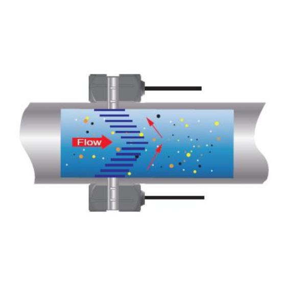
Doppler Ultrasonic Flowmeter DF6100-EP Manual PART 1 INTRODUCTIONS 1.1 PRINCIPLE The Doppler ultrasonic flow meter is designed to measure volumetric flow of liquid within closed conduit, the pipe line must be filled full of liquids, there must be a certain amount of bubbles or suspended solids in liquid. -
Page 4: Notes For Application
Doppler Ultrasonic Flowmeter DF6100-EP Manual 1.3 NOTES FOR APPLICATION When installing transducers, it need enough straight pipe; When straight pipe is not enough, by setting menu SERVICE, the flowmeter will still get high accuracy, and obtain a more accurate reading. more details, please see 4.3.16 SERVICE mode;... -
Page 5: Technical Specifications
Doppler Ultrasonic Flowmeter DF6100-EP Manual 1.4 TECHNICAL SPECIFICATIONS 1.4.1 TRANSMITTER Doppler ultrasonic Measurement principle Resolution 0.25mm/s Repeatability 0.2% of reading 0.5% -- 2.0% F.S. Accuracy 2-60s for optional Response time Flow Velocity Range 0.05- 12 m/s Liquid Types Supported Liquids containing 100ppm of reflectors and at least 20% of the reflectors are larger than 100 micron. -
Page 6: Part 2 Portable Transmitter
Doppler Ultrasonic Flowmeter DF6100-EP Manual PART 2 PORTABLE TRANSMITTER 2.1 TRANSMITTER Fig 2.1 Portable flow meter One standard set of product includes: Soft case, portable transmitter, standard transducers, couplant, stainless steel belt, charger, 4-20mA output cable terminals, etc. The flow meter is equipped with a rechargeable lithium battery. This battery will require charging before initial operation. -
Page 7: Output Interfaces
Doppler Ultrasonic Flowmeter DF6100-EP Manual • If the portable flow meter is stored for prolonged periods of time, had better store at a temperature below 21ºC. • Try to avoid the meter working while battery charging. 2.2 OUTPUT INTERFACES Brown:4-20mA Red:4-20mA... -
Page 8: Relay Output
Doppler Ultrasonic Flowmeter DF6100-EP Manual 2.2.2 Relay output (If portable flow meter needs this functionality, please make a statement when placing orders) Please refer to 4.3.14 Dual Relay Configuration to see Menu Configuration. The relay operations are user configured via the front panel to act in flow rate alarm or error alarm, power supply interruption alarm and totalizer pulse. -
Page 9: Part 3 Clamp-On Transducer Installation
Doppler Ultrasonic Flowmeter DF6100-EP Manual PART 3 CLAMP-ON TRANSDUCER INSTALLATION 3.1 TRANSDUCER MOUNTING LOCATION Placement of the ultrasonic transducer is the most critical step in achieving an accurate and reliable flow reading. All flow meters of this type rely on a full-pipe of fluid that is flowing symmetrically (evenly) in the pipe. -
Page 10: Transducer Installation Procedures
Doppler Ultrasonic Flowmeter DF6100-EP Manual 3.2 TRANSDUCER INSTALLATION PROCEDURES Locate the reference mounting positions of 3 and 9 o’clock (180° symmetrically) as shown in Fig 3.1. Fig 3.1 Two transducers must be installed 180° symmetrically. Two transducers called A and B transducer, A is transmitting transducer and B is receiving transducer, they must be installed 180°... -
Page 11: Transducer Installation
Doppler Ultrasonic Flowmeter DF6100-EP Manual Mounting of high temperature transducers is similar to Doppler flow meter standard transducers. High temperature installations require acoustic couplant Dow Corning 112 that is rated not to flow at the temperature that will be present on the pipe surface. -
Page 12: Part 4 Instrument Programming
Doppler Ultrasonic Flowmeter DF6100-EP Manual PART 4 INSTRUMENT PROGRAMMING 4.1 GENERAL The Doppler flow meter contains a four-key tactile feedback keypad interface that allows the user to view and change configuration parameters used by the Doppler flow meter operating system. -
Page 13: Numeric Value Entry Procedure
Doppler Ultrasonic Flowmeter DF6100-EP Manual 4.2.2 Numeric Value Entry Procedure NOTE: If you are already in PROGRAM mode and the selection to be viewed or changed is already displayed, proceed to step 3 below. If you are in PROGRAM mode and the selection to be viewed or changed is not displayed, press the UP or DOWN arrow keys and repeat pressing until the desired selection appears. -
Page 14: Pipe Inside Diameter
Doppler Ultrasonic Flowmeter DF6100-EP Manual 4.3.3 Pipe Inside Diameter PIPE ID – Pipe Inside Diameter Entry According to ID UNIT, display . Enter the pipe inside diameter in inches if ID INCH or ID MM INCH was selected in ID UNIT; in millimeters if MM was selected. -
Page 15: Engineering Units Totalizer
Doppler Ultrasonic Flowmeter DF6100-EP Manual DAY - Days SEC - Seconds Select a desired engineering unit for flow rate measurements. 4.3.7 Engineering Units TOTALIZER TOTL UNT – Engineering Units for Flow Totalizer GALLONS - U.S. Gallons LITERS - Metric Liters MGAL - Millions of U.S. -
Page 16: Low Flow Cut-Off
Doppler Ultrasonic Flowmeter DF6100-EP Manual 4.3.10 Low Flow Cut-off FL C-OFF – Low Flow Cut-off A Low Flow Cut-off entry is provided to allow very low flow rates (that can be present when pumps are off and valves are closed) to be displayed as Zero flow. -
Page 17: Dual Relay Configuration
Doppler Ultrasonic Flowmeter DF6100-EP Manual CAL 4MA CAL 20MA 4-20 TEST 4-20mA Span The FLOW 4MA and FLOW 20MA entries are used to set the span of the 4-20mA analog output. These entries are volumetric rate units that are equal to the volumetric units configured as Engineering Rate Units and Engineering Units Rate Interval. -
Page 18: Change Password
Doppler Ultrasonic Flowmeter DF6100-EP Manual FLOWALM is corresponding to Wiring terminal “RELAY -, +”, only can be user configured as flow rate alarm, error alarm, or power supply interruption alarm output. Flow Rate Relay configuration permits relay changeover at two separate flow rates allowing operation with an adjustable switch deadband. - Page 19 Doppler Ultrasonic Flowmeter DF6100-EP Manual 1. AGC MODE –Gain Control Mode of Operation NORMAL - Factory default Settings, Automatic Gain Control Mode, Used for generally conditions HIGH - Automatic Gain Control Mode, Used for low signal strength conditions MANUAL - Manual Gain Control Mode, AGC disabled, Used for not enough straight pipe...
-
Page 20: Operating Instruction
Doppler Ultrasonic Flowmeter DF6100-EP Manual The selection invokes optimum hardware and software settings unique to the transducer architecture. 5. LINEAR – Entry of Linearization Data (Users do not need to modify the data, Please consult factory technical personnel in specific... -
Page 21: Part 5 Warranty And Service
Doppler Ultrasonic Flowmeter DF6100-EP Manual PART 5 WARRANTY AND SERVICE 5.1 WARRANTY The manufacturer provides one year warranty on all products, free of charge, but the users should be responsible for the one-way transportation fee from the customer to the factory. - Page 22 SERIES DF6100-EP SOFTWARE MAP - General Operations ID UNIT (Pipe Measurement Units) TOTL UNT (Flow Totalizer Units) PASSWORD (Locks Keypad) XXXX (Other than 0000—Locks Keypad) INCH (Inches) GALLONS 0000 (Keypad Unlocked) MM (Millimeters) LITERS MGAL (Million Gallons) CUBIC FT (Cubic Feet)
- Page 23 SERIES DF6100-EP SOFTWARE - Output Configuration Map From “General Operations” Software Map 4-20MA FLOW 4MA (Flow Rate at 4 mA output) Configuration of Output 1 and 2 are essentially identical, so FLOW20MA (Flow Rate at 20 mA output) only Output 1 configuration is detailed.
- Page 24 Fluid Properties Fluid Specific Gravity Sound Speed delta-v/degree C Kinematic Viscosity Absolute Viscosity 20 degrees m/s/degree C Centistok Centipoi Acetate, Butyl 1270 4163. Acetate, Ethyl 0.901 1085 3559. 0.489 0.441 Acetate, Methyl 0.934 1211 3973. 0.407 0.380 Acetate, Propyl 1280 4196.
- Page 25 Oil, Castor 0.97 1477 4845.8 Oil, Diesel 0.80 1250 4101 Oil (Lubricating X200) 1530 5019.9 Oil (Olive) 0.91 1431 4694.9 2.75 100.000 91.2 Oil (Peanut) 0.94 1458 4783.5 Paraffin Oil 1420 4655.7 Pentane 0.626 1020 3346.5 Petroleum 0.876 1290 4229.5 1-Propanol 0.78 1222...
- Page 26 Steel, Stainless Steel, P.V.C. Standard Schedules SCH. 10 SCH.5 SCH.20 SCH.30 STD. SCH. 40 SCH. 60 X STG. SCH. 80 SCH. 100 SCH. 120 SCH. 140 SCH. 180 (LTWALL) Nominal OUTSIDE Pipe Size DIAMETER Inches Wall Wall Wall Wall Wall Wall Wall Wall...
- Page 27 Cast Iron Pipe Standard Classes CLASS A CLASS B CLASS C CLASS D CLASS E CLASS F CLASS G CLASS H O.D. I.D. Size O.D. I.D. O.D. I.D. O.D. I.D. O.D. I.D. O.D. I.D. O.D. I.D. O.D. I.D. Wall Wall Wall Wall Wall...
- Page 28 Ductile Iron Pipe Standard Classes CementLining Pipe Outside Std./Double Class 50 Class 51 Class 52 Class 53 Class 54 Class 55 Class 56 Size Diameter Thickness (inches) (inches) ID Wall Wall ID Wall ID Wall ID Wall Wall Wall 6.40 0.25 3.96 3.46 0.25...
- Page 29 FPS TO GPM CROSS - REFERENCE (Schedule 40) Nominal I.D. Pipe (Inches) 1.05 2.6989 4.0484 5.3978 6.7473 8.097 9.4462 10.796 12.145 13.490 14.844 16.190 17.540 18.890 20.240 21.590 22.941 24.290 1.25 1.38 4.6620 6.9929 9.3239 11.655 13.99 16.317 18.648 20.979 23.310 25.641 27.970...
- Page 30 FPS TO GPM CROSS - REFERENCE (Schedule 40) Nominal I.D. Pipe (Inches) 16.88 697.52 1046.3 1395.0 1743.8 2093.0 2441.3 2790.1 3138.8 3488.0 3836.3 4185.0 4534.0 4883.0 5231.0 5580.0 5928.9 6277.7 18.81 866.14 1299.0 1732.0 2165.3 2598.4 3031.5 3464.6 3897.6 4330.7 4763.8 5196.8 5629.9...
- Page 31 Lanry Instruments (Shanghai) Co.,Ltd Add: 6 Floor , Block F,Bldg 5,No.2800 Jiuxin Rd., Songjiang District, Shanghai 201612,China Tel:86 21-67801665,67618991 Fax:86 21-67801625 http://www.lanry-flow.com...
Need help?
Do you have a question about the DF6100-EP and is the answer not in the manual?
Questions and answers