Columbia Chariot CR-10 Operation, Maintenance And Service Manual
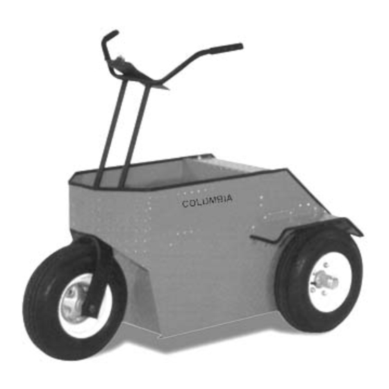
12 volt personnel carrier stand up operation
Hide thumbs
Also See for Chariot CR-10:
- Owner's manual (23 pages) ,
- Service manual (23 pages) ,
- User manual

Related Manuals for Columbia Chariot CR-10


Summary of Contents for Columbia Chariot CR-10
- Page 1 Industrial & Commercial Vehicles CR-10 Chariot 12 Volt Personnel Carrier Stand Up Operation Operation, Maintenance And Service Manual With illustrated parts list 11/01 REV A 99485-00...
- Page 2 (800) 222-4653 * Web: www.parcar.com E-Mail: info@parcar.com Your decision to invest in a Columbia Industrial Vehicle is very gratifying to us and we wish you many years of satisfaction Columbia ParCar Corp. A member of the Nordic Group of Companies 350 N.
- Page 3 Secondly, it will acquaint the reader with the construction of Columbia Industrial vehicles and assist him /her in performing basic maintenance and repair. We sincerely believe that this manual will make your association with Columbia Industrial vehicles more pleasant and profitable.
-
Page 4: Table Of Contents
Table of Contents CHAPTER 1 - INTRODUCTION Warnings and Dangers Vehicle Description & Specifications Lifting Instructions Receipt of Vehicle CHAPTER 2 - OPERATION INFORMATION Safety Instructions Rules & Guidelines Driver Training Program Driver Qualifications ... - Page 5 Table of Contents (cont.) Front Fork Front Fork Removal 3-13 Front Fork Installation Front Wheel/Hub Removal Front Wheel/Hub Installation Rear Suspension Rear Wheel/Hub Removal 3-13 Rear Wheel/Hub Installation 3-14 Mechanical Controls ...
-
Page 6: Chapter 1 - Introduction
Safety Standards or EPA regulations, and are not equipped for operation on public streets, roads, or highways. To the best knowledge of Columbia ParCar Corp., the material contained herein is accurate as of the date this publication was approved for printing. Columbia ParCar Corp. is not liable for errors in this manual or for incidental or consequential damages that result from the use of the material in this manual. -
Page 7: Vehicle Description & Specifications
Chapter 1 Introduction PAGE # WARNINGS & DANGERS VEHICLE DESCRIPTION & SPECIFICATIONS LIFTING INSTRUCTIONS RECEIPT OF VEHICLE... - Page 8 Accordingly, anyone who uses a service procedure or tool which is not recommended by Columbia Industrial Vehicle must first thoroughly satisfy himself that neither his nor the operator's safety will be jeopardized by the service methods selected.
- Page 9 A running vehicle must be worked on with the greatest care. Use caution and common sense. Working on Columbia Industrial Vehicles without following proper procedures and using proper lifting equipment may result in vehicle damage or personal injury.
- Page 10 ALL VEHICLES Always wear safety glasses or approved eye protection while servicing vehicle. Wear a full face shield when working with batteries Exceeding rated vehicle load capacities could result in possible severe injury or property damage. WARNING Always turn key switch to OFF, remove key, block tires and disconnect the (CONT.) battery negative (-) cable before performing any vehicle service to avoid accidental start-up of vehicle and possible injury...
- Page 11 Electric Utility Vehicle Information: Vehicle Identification Number (V.I.N.) 4R-12345 Rated Capacity Including passengers and Operator 350lbs. (158kg) Operating Weight: 375 lbs. (170kg) Without Batteries: 248 lbs. (113kg) Maximum Service Weight of Batteries: 127 lbs. (58kg) This Carrier is Designed for 12 V (Normal) Designed to conform with the Mandatory Requirements of ASME/ANSI B56.8 Part III, ANSI/UL 583 Type E And OSHA 1910.178...
- Page 12 Tire description Range ‘C’ pneumatic Notes: Columbia Industrial Vehicles are designed to conform with ANSI B56.8 and OSHA standards. Columbia ParCar Corp. reserves the right to change specifications, equipment or designs at any time without notice and without incurring obligations.
-
Page 13: Lifting Instructions
What to do if you find a problem: 1. If vehicle has just been delivered, report any physical damage or missing items to the Shipping Company and your local Columbia Industrial Vehicle Dealer. Look for body damage, jagged edges etc. that may cause personal injury. - Page 14 DANGER: If any problems are found, DO NOT operate vehicle until repairs are made. Failure to make necessary repairs could result in fire, severe personal injury, property damage or death. Consult your local Columbia Industrial Vehicle Dealer for professional service.
-
Page 15: Safety Instructions
Chapter 2 Operator information PAGE # SAFETY INSTRUCTIONS Rules & Guidelines Driver Training Program Driver Qualification SAFETY COMMITTEE VEHICLE CONTROLS VEHICLE OPERATING INSTRUCTIONS VEHICLE STORAGE... -
Page 16: Driver Qualifications
Operator Safety Instructions Note: It is the responsibility of the owner or leasee of this vehicle to assure that the operator understands the various controls and operating characteristics of this vehicle. as well as, obeying the following safety rules and guidelines (extracted from the American National Standards Institute personnel and burden carriers ANSI B56.8). - Page 17 These basic rules of operation, combined with courtesy and common sense, will help make driving your Columbia Industrial vehicle a safe and pleasant experience. The safety committee should be made up of managers and/or supervisors in charge or responsible for the operation and...
-
Page 18: Vehicle Controls
Vehicle Controls Figure 1 - CR-10 Controls The following describes the use of each control on this vehicle. Note: Some controls are optional equipment and may not be installed on this vehicle. 1 - Key Switch: A key-switch located on the right side of the charger faceplate energizes the vehicle. Rotate the key clockwise to turn the vehicle on, counterclockwise to turn the vehicle off. - Page 19 The forward – reverse switch should be in the neutral position with the park brake set and key switch in OFF, whenever the operator disembarks from the vehicle. Warning: B e sure to have both hands on the handlebars at all times. 3 - Accelerator / Brake Actuation: Tilting the foot treadle platform controls acceleration and braking.
-
Page 20: Vehicle Operation Instructions
Vehicle Operating Instructions Driving: Do not operate this vehicle unless you are a qualified and trained operator. Keep the vehicle under control at all times. Drive only on level surfaces or on surfaces having an incline of no more than 10%. ... - Page 21 The batteries should be recharged as necessary to resume specific gravity to fully recharged levels-approximately 1.260. Fully charged batteries should be stored in a cool environment. Warning: Turn key switch “OFF” and remove key during storage to prevent unintentional starting of vehicle. DO NOT attempt to charge a battery that is frozen or if battery case is excessively bulged.
- Page 22 Returning vehicle to service: 1. Fully recharge batteries. 2. Check tire pressure and readjust if necessary, refer to manufactures recommendation imprinted on tire sidewall for the 4.80 x 8 tires. 3. Perform initial maintenance per periodic maintenance chapter 3. 4. Test drive vehicle before returning to service.
-
Page 23: Checklist
Chapter 3 Maintenance and Service Page # Maintenance Guidelines Checklist Troubleshooting Guide Recommended Spare Parts Maintenance Procedures Battery Care Electric Vehicle Battery Battery Removal Battery Installation Battery Charger operations Battery Testing Drive Motor Removal Installation Brush Removal 3-10 Brush Installation Brakes 3-10 Brake Adjustment... - Page 24 Rear Suspension 3-13 Wheel/Hub Removal Wheel/Hub Installation 3-14 Mechanical Controls 3-14 Treadle/Rear Spindle Removal Treadle/Rear Spindle Installation Handlebar Removal Handlebar Installation 3-15 Charger 3-15 Charger Removal Charger Installation...
-
Page 25: Maintenance Guidelines
Maintenance Guidelines To ensure that the Model CR-10 Personnel Carrier is kept in a safe and correct operating condition, the carrier must be inspected and maintained on a regular basis. Proper lubrication, electrical control adjustments, safety feature checks, etc. performed at recommended intervals will help prevent damage or failure of the unit while providing optimum performance. - Page 26 Checklist Before operating the vehicle inspect vehicle for damage, check operating controls (including Reverse warning alarm if applicable), check tires for proper inflation and test drive. Maintenance Checklist Maintenance or Service operation Weekly Monthly Quarterly Annual Battery Check electrolyte level. Add distilled water only See Batteries Clean battery area with a soda (Bicarbonate) and distilled water solution...
-
Page 27: Troubleshooting Guide
See speed control section page 3-6 Wiring Check for loose wires or faulty connections If these test procedures do not resolve your vehicle problem contact your local Columbia Industrial Vehicle Dealer or contact Columbia ParCar. Recommended Spare Parts Recommended spare parts list... -
Page 28: Maintenance Procedures
Maintenance Procedures Battery Care Electric Vehicle Battery The storage battery receives, stores, and delivers electrical power. This receiving, storing, and delivering of electrical power is called a cycle. Receive - Charging vehicle batteries. Store - Vehicle standing idle. ... -
Page 29: Removal
To install the batteries reverse the removal procedure. Battery Charger Operating Instructions: The built-in battery charger is custom made for Columbia Industrial Vehicle CR-10 Model. Its operation is totally automatic. Refer to chapter 5 for for charger operating procedures When connected to a 110 - 120 Volt AC power source, the charger's electronic timer will turn the charger on. -
Page 30: Battery Testing
Batteries (cont.) CAUTION Charge in well-ventilated areas. Charging batteries can emit explosive gases. Keep clear of sparks and open flame. Battery Testing Specific Gravity Test: It is possible to estimate a battery’s ability to perform by measuring the specific gravity of each cell with a hydrometer. -
Page 31: Interpretation Of Hydrometer Readings
Battery Testing (cont.) Interpretation of Hydrometer Readings: State of charge: Check specific gravity of each cell. Refer to table below: State of Charge Specific Gravity (80º F) 100% 1.250-1.270 1.220-1.240 1.190-1.210 1.160-1.180 Condition: If the difference between the highest and lowest cell is .050 (50 points) or more, the battery is nearing the end of its useful life and should be replaced. -
Page 32: Motor Brush Removal
Drive Motor (cont.) 3. Install the rear drive wheel. Torque wheel nuts in a crossing pattern, to 65-ft. lbs. 4. Connect the wire leads to the motor. Motor Brush Removal: See page 4-4 chapter 4, for exploded view and parts breakdown 1. -
Page 33: Brake Installation
Brakes (cont.) Brake Installation: 1. Install the brake backing plate spacer and the brake backing plate. Use a thread-locking compound on the brake backing plate retainer screws and tighten the screws, then loosen each screw 1/4 turn. 2. Connect the upper end of the treadle to the brake assembly linkage and torque the nut to 120 inch Pounds. -
Page 34: Drive Chain
Drive Chain Drive Chain Removal: 1. Loosen drive motor tightness adjustment bolt located below kneepad on right side of vehicle. 2. Loosen the four (4) drive motor mounting bolts. See figure 7B. 3. Rotate drive motor to back. 4. Remove drive train. Drive Chain Installation: 1. -
Page 35: Front Fork
Front Fork Front Fork Removal: See page 4-7 chapter 4, for exploded view and parts breakdown Place the front of the vehicle frame on blocks to allow for wheel removal. Follow the procedures outlined in handlebar removal on page 4-14. Remove the front fork spindle nut with a Wheel 1-1/2"... -
Page 36: Rear Wheel/Hub Installation
Rear Suspension (cont.) Rear Wheel / Hub Installation 1. Install the hub on the spindle. On the drive wheel side it will be necessary to depress the treadle before the hub with drum/sprocket assembly can be installed. 2. Install the castle nut on the spindle. Torque the castle nut to 120 inch pounds and then back the castle nut off two slots and Install the cotter pin. -
Page 37: Handlebar Installation
Mechanical Controls (cont.) Handlebar Installation: Note: Make sure that the handlebars and front fork spindle are properly aligned 1. Push the handlebar onto the fork spindle. 2. Install the handlebar retainer nut, align handle bars to front fork and torque to 200 foot pounds. 3. -
Page 38: Body Items
Chapter 4 Illustrated Parts List Page # BODY ITEMS Parts List Schematic MOTOR Parts List Schematic DRIVE HUB & BRAKES Parts List Schematic FRONT FORK ASSEMBLY Parts List Schematic SPEED CONTROL SWITCH Parts List Schematic ELECTRICAL, STANDARD 4-10 Parts List Schematic ELECTRICAL, FORWARD &... - Page 39 Body Items Body Parts List Item # Part Number Description Qty. Used 19201-00 Body Complete 51301-00 Cover Control 3987-BS Cap Screw Cover to Body – 5/16-18 x .3/4” 6702-B Washer, Flat, 1/4" 7041-B Lock washer, 1/4” 11735 Nut, Tinnerman – Clipped to Body Frame 47965-00 Fender, L.H.
- Page 40 Body Items (cont.)
- Page 41 Traction Motor 12V Motor Parts List Item # Part Number Description Qty. Used 69400-00 Motor, Traction 12V Headband, Inspection Commutator End Frame Bearing Washer, Spring Brush Holder Plate 11839 Brush Spring Field Coil Assembly Brush Nut/Washer Package Pole Screw Armature Assembly 83285-89A Ring, Retaining 83286-89A...
-
Page 42: Drive Hub & Brake
Drive Hub and Brake... - Page 43 Drive Hub and Brake Drive Hub and Brake Parts List (See page 4.5) Qty. Item # Part Number Description Used 56803-00 Spindle Assembly 33403-00 Spacer, Brake 7041-B Lockwasher, 5/16 3987-BS Screw, Hex Cap 5-16-18x3/4” 56806-00 Rod End Bearing 1/4-28, Male, Ball Joint 3993 Screw, Hex Cap 1/4-20x1 1/4”...
-
Page 44: Front Fork Assembly
Front Fork Assembly Front Fork Parts List Qty. Item # Part Number Description Used 19203-00 Front Suspension Complete (Incl Items 2 – 16) 56800-00 Fork Assembly, Front 9080 Bearing, Roller - Fork 9081 Bearing, Roller, Race - Fork (Not Shown) 56830-00 Dust Cover (Retainer, Bearing) 56838-00... -
Page 45: Speed Control Switch
Speed Control Switch... - Page 46 Speed Control Switch (cont.) Speed Control Switch Parts List Item # Part Number Description Qty. Used 69721-00 Switch Assy, Speed Control 2339 Screw, Machine 10-24 x 3/4 7620-W Nut, Hex #10-24 7118 Washer, #10 External Tooth 1005 Screw, Machine 10-24 x 1-1/4 6034 Washer, Brass (Nylon) 6032...
-
Page 47: Electrical Schematic, Standard
Electrical Schematic, Standard VIN # 4R-11100 to 4R11292 Electrical, Standard Parts List Item # Part Number Description Qty. Used 69826-00 Panel, Speed Switch 66014-84 Battery, 220amp T-105 66016-96 Battery, 244amp T145 69709-00 Solenoid, 12v 74591-96 Circuit Breaker, Horn 69001-76A Horn, 12V 69400-00 Motor, Traction 12V 69706-00... -
Page 48: Electrical Schematic, Forward / Reverse Option
Electrical, Forward/Reverse Option VIN # 4R-11100 to 4R11292 Electrical, Forward/Reverse Option Parts List Item # Part Number Description Qty. 69826-00 Panel, Speed Switch 66014-84 Battery, 220 amp T105 66016-96 Battery, 244 amp T145 69823-00 Solenoid, Forward / Reverse 74591-96 Circuit Breaker, Horn 69001-76A Horn, 12V 69400-00... -
Page 49: Electrical Schematic, New Keyswitch
Electrical Schematic, New Keyswitch VIN # 4R-11293 to 4R-____________ Electrical, Standard Parts List Item # Part Number Description Qty. Used 69826-00 Panel, Speed Switch 66014-84 Battery, 220 amp T105 66016-96 Battery, 244 amp T145 69709-00 Solenoid, 12v 74591-96 Circuit Breaker, Horn 69001-76A Horn, 12V 69400-00... -
Page 50: Electrical Schematic, Forward / Reverse Option (New Keyswitch)
Electrical Schematic, New Keyswitch, Forward/Reverse Option VIN # 4R-11293 to 4R-____________ Electrical, Forward/Reverse Option Parts List Item # Part Number Description Qty. 69826-00 Kit, Speed Switch Panel 66014-84 Battery, 220 amp T-105 66016-96 Battery, 244 amp T145 69822-00A Solenoid, Forward / Reverse 74591-96 Circuit Breaker, Horn 69001-76A... -
Page 51: Charger Information
Chapter 5 APPENDICES PAGE # BATTERY CHARGER OVERVIEW Charger Information Theory of Operation OPERATING INSTRUCTIONS Initial Inspection Mounting Location Connections Operation Troubleshooting Chart Schematic diagram Charger Parts list... - Page 52 Verify data to insure that the proper DC voltage matches the battery to be charged. If not contact your Columbia ParCar Dealer. Mounting Location and Connections: (See 4-14 Chapter 4) 1. Mount charger to mounting holes on charger panel.
- Page 53 Battery Charger Information (cont.) 2. After a short time delay, Approximately 5 to 6 seconds, the charger will automatically turn on. 3. A RED light will indicate normal charge and the charger will begin to charge the batteries. 4. Charger will remain charging until the solid state circuitry senses the battery is fully charged. At which the charger automatically turns off.
- Page 54 Battery Charger Information (cont.) Figure 1 – Battery Charger Schematic Charger Parts List Item # Part Number Description 66600-00 Charger, Complete w/Cord 66620-00 Charger Face Panel 66621-00 Transformer 66622-00 Auto-Start Control Board 66623-00 Capacitor 66624-00 AC Input Receptacle 66625-00 Rectifier 66626-00 Heatsink 66627-00...
- Page 55 Industrial & Commercial Vehicles 350 N. Dewey P.O. Box 30 Reedsburg, WI 53959 Phone (608) 524-8888 Toll-Free (800) 222-GOLF Fax (608) 524-8380 Web www.parcar.com E-Mail infoparcar@parcar.com, techsupport@parcar.com...
Need help?
Do you have a question about the Chariot CR-10 and is the answer not in the manual?
Questions and answers