Columbia CR-10 Chariot Service Manual
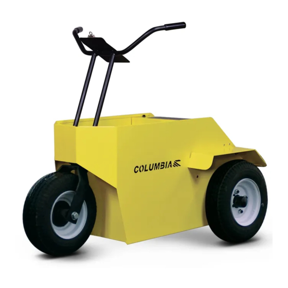
Electric golf cart
Hide thumbs
Also See for CR-10 Chariot:
- Owner's manual (23 pages) ,
- Operation, maintenance and service manual (55 pages) ,
- User manual
Table of Contents
Advertisement
Advertisement
Table of Contents

Related Manuals for Columbia CR-10 Chariot


Summary of Contents for Columbia CR-10 Chariot
- Page 2 To ensure a satisfactory and lasting repair job, follow the service manual instructions carefully and use only genuine Columbia Industrial Commercial Vehicle replacement parts. This is your insurance that the parts you are using will fit right, operate properly and last longer. When you use genuine Columbia Industrial Commercial Vehicle parts, you use the best.
-
Page 3: Table Of Contents
Table of Contents FOREWARD CHAPTER 1 - SAFETTY 1.1 Overview 1.2 Symbols in Procedures 1.3 Safety Information 1.4 Safety Concerns 1.5 Lifting Instructions CHAPTER 2 - GENERAL INFORMATION 2.1 Vehicle Description 2.2 Vehicle Identification Number (VIN) 2.3 VIN Matrix 2.4 Vehicle Specification 2.5 Vehicle Controls 2.5.1 Keyswitch 2.5.2 Battery State of Charge Meter... -
Page 4: Overview
Accordingly, anyone who uses a service procedure or tool which is not recommended by Columbia ParCar must first thoroughly satisfy him/herself that neither their nor the operator’s safety will be jeopardized by the service methods selected. - Page 5 Follow all procedures exactly and observe all warnings stated in this manual. Use caution and common sense. Proper service and repair is important for safe, reliable operation of all Columbia Industrial/Commercial vehicles. The service procedures recommended and described in this service manual are effective methods for performing service operations.
-
Page 6: Safety Concerns
1.4 SAFETY CONCERNS It is recommended that the operator, owner or renter of this vehicle comply with the OSHA requirements as stated in the Code of Federal Regulations, Section 29, 1910.178, Powered Industrial Truck Training Standard and the ANSI requirements as stated in Personnel and Burden Carriers ANSI B56.8. As a minimum every operator should, in addition to the above requirements found in the standards noted above: ... -
Page 7: Chapter 2 - General Information
The VIN is also stamped on the metal cross bar located under the foot treadle platform. See Figure 1.3.2. To ensure prompt service when repairs or adjustments are required, your Columbia Dealer must have the VIN. Figure 2.2.2 CR1A1-0ZJ1234 is an example of a current VIN. -
Page 8: Vehicle Controls
2.4 VEHICLE SPECIFICATIONS Passenger Capacity Max. Speed (MPH) Turning – Curb to Curb (in) Turning –Intersecting Aisle (in) Overall Length (in) Overall Width (in) 29.5 Overall Height (in) Wheelbase (in) Load Bed Height (in) Load Bed – LxW (in) 18x16 2.5 VEHICLE CONTROLS This section describes the operating controls of the vehicle. -
Page 9: Battery State Of Charge Meter
2.5.7 WARNING LABEL and OPERATING INSTRUCTION - Fig. 2.5.1 G & H Read the warning label and operating instruction information carefully before operating the vehicle. Do not remove any nameplate, warnings, or instructions affixed to your Columbia Vehicle. Promptly replace any that become damaged or removed. Contact Columbia ParCar for replacements. -
Page 10: Steering Handle Bars
2.5.9 STEERING HANDLE BARS – NOT SHOWN The steering system is designed to operate as a bicycle does. The vehicle will turn to the same direction as the handle bar. Be sure to have both hands on the handlebars at all times. Do not turn the vehicle sharply at high speeds. -
Page 11: Parking
2.8 PARKING If you will be away from this vehicle turn off the keyswitch, remove the key and take the key with you. If you park this vehicle on an incline, block the wheels. Do not block fire aisles, fire equipment, or stairways. -
Page 12: Chapter 3 Electric System
3 ELECTRIC SYSTEM 3.1 IMPORTANT INFORMATION The type of battery used in a Columbia vehicle has a service requirement which is quite different from that of an automotive battery. The electric vehicle battery supplies all of the power to drive the vehicle. During operation the power stored in the batteries is expended. -
Page 13: Battery Disconnect Methods
NOTICE: Automotive batteries should never be used for "deep cycle" application, as their useful life will be very short. Install surge arrestors on incoming AC power lines. Surge arrestors will help protect electrical/electronic components in the charger and vehicle from all but direct or “close proximity”... -
Page 14: Battery Cleaning
Figure 3.4.1 Do not overfill batteries. Electrolyte expands and can overflow during charging. Water added to replace the spillage dilutes the electrolyte and reduces its specific gravity. Use only distilled water. Vehicle batteries may use up to 16 quarts of water during their useful life and non-distilled water may contain harmful minerals which will have a cumulative adverse effect on battery performance and life. -
Page 15: Charger Information
3.7 CHARGER INFORMATION The built-in battery charger is custom made for Columbia vehicle CR-10 Models. Its operation is totally automatic. When connected to a 110 - 120 Volt AC power source, the charger's electronic timer will turn the charger on. -
Page 16: Specific Gravity Test
3.11 SPECIFIC GRAVITY TEST It is possible to determine a battery's ability to perform by measuring the specific gravity (sp. gr.) of each cell with a hydrometer. This is the best method to determine a defective battery. The hydrometer readings indicate two things: ... -
Page 17: Maintenance Guidelines
4.0 SERVICING 4.1 MAINTENANCE GUIDELINES To ensure that the vehicle is kept in a safe and correct operating condition, it must be inspected and maintained on a regular basis. Proper lubrication, electrical control adjustments, safety feature checks, etc. performed at recommended intervals will help prevent damage or failure of the unit while providing optimum performance. - Page 18 To remove the brakes (See Figure 4.2.3): Raise and block up the rear of the vehicle. On the drive wheel side, remove the drive chain master link (A) and the drive chain. Remove the four wheel lug nuts holding the rear wheels to the rear hubs and remove the wheels. ...
-
Page 19: Front Fork Assembly
4.3 FRONT FORK ASSEMBLY - Figure 4.3.1 To remove fork and handle bar: Place the front of the vehicle frame on blocks to allow for wheel removal. Remove the handlebar-retaining nut (A) with a 1-1/2" socket. Carefully pull the handlebar upward with slight side to side motion to remove the handlebar from the fork spindle. -
Page 20: Drive Motor
Tension Adjustment: Lift the rear of the vehicle and remove the drive wheel. Loosen the 4 drive motor mounting bolts (Fig. 4.4.2) and jam nut on the drive motor adjusting screw. Turning motor adjusting screw towards motor will tighten drive chain. -
Page 21: Speed Control Switch
4.6 SPEED CONTROL SWITCH –Figure 4.6.1 Remove battery cables before starting work on the electrical system. Slide Maintenance Lubricate the 3 contact bars (A) where the "L" brush (B) slides with good bearing grease. DO NOT use a graphite type grease. DO NOT use metal objects to apply grease to the switch. -
Page 22: Treadle
4.8 TREADLE – Figure 4.8.1 To remove: Follow the steps for rear wheel hub removal in Section 4.7. Disconnect the speed control arm (A) from the front of the treadle. Disconnect the treadle to brake linkage from the treadle. -
Page 23: Cleaning
To install: Place the charger in the vehicle. Install the bottom two charger mounting screws. Do not tighten. Connect the wires to the battery state of charge meter and keyswitch. Connect the charger DC output leads to the solenoid and motor. ...
Need help?
Do you have a question about the CR-10 Chariot and is the answer not in the manual?
Questions and answers