
Related Manuals for Parker PVSG-IQAN-C2E1M2W1U1


Summary of Contents for Parker PVSG-IQAN-C2E1M2W1U1
- Page 1 Parker Gateway for Mobile IoT Solution North/Central/South Americas PVSG-IQAN-C2E1M2W1U1 Europe/Australia/New Zeland/International PVSG-IQAN-C2E1M3W1U1 U s e r G u i d e...
- Page 2 Offer of Sale The items described in this document are hereby offered for sale by Parker Hannifin Corporation, its subsidiaries or its authorized distributors. This offer and its acceptance are governed by the provisions stated in the "Offer of Sale" elsewhere in...
-
Page 3: Table Of Contents
Safety during installation ........................viii Safety during start-up ........................viii Safety during maintenance and fault diagnosis ..................ix 1. About the PVSG-IQAN (Parker Vehicle System Gateway with IQAN Integration) ......1 1.1. Remote Monitoring Capabilities ..................... 2 1.1.1. Integrate CAN based signals ..................... 2 1.1.2. - Page 4 Contents 3. Mounting the PVSG-IQAN to a Vehicle .................. 26 3.1. Dimensions ..........................27 3.2. Designing and Connecting the Vehicle Harness ................28 4. Gateway Connections (Pinout) ..................... 29 4.1. Power and Vehicle Communication ....................29 4.1.1. Mating Connector ......................29 4.1.2.
-
Page 5: Publication History
Add part number 166034 in section 1.4 6-10-2020 Added information of new tiering services and European gateway support 5-19-2021 Correct 2yr and 3yr part number and PVSG abbreviations 8-01-2021 Adding User Experience 2.0 screens and onboarding steps Edit the knowledge base link to Parker Community. -
Page 6: Safety
Contact the manufacturer if there is anything you are not sure about or if you have any questions regarding the product and its handling or maintenance. The term "manufacturer" refers to Parker Hannifin Corporation. Safety symbols The following symbols are used in this document to indicate potentially hazardous... -
Page 7: General Safety Regulations
Safety General safety regulations Work on the hydraulics control electronics may only be carried out by trained personnel who are well-acquainted with the control system, the machine, and its safety regulations. Follow the manufacturer's regulations when mounting, modifying, repairing, and maintaining equipment. The manufacturer assumes no responsibility for any accidents caused by incorrectly mounted or incorrectly maintained equipment. -
Page 8: Welding After Installation
Safety Welding after installation Complete as much as possible of the welding work on the chassis before the installation of the system. If welding must be done afterwards, proceed as follows: Do not place the welding unit cables near the electrical wires of the control system. -
Page 9: Safety During Maintenance And Fault Diagnosis
Safety Safety during maintenance and fault diagnosis Before performing any work on the hydraulics control electronics, ensure that The machine cannot start moving. ▪ Functions are positioned safely. ▪ The machine is turned off. ▪ The hydraulic system is relieved from any pressure. ▪... -
Page 10: About The Pvsg-Iqan (Parker Vehicle System Gateway With Iqan Integration)
1. About the PVSG-IQAN (Parker Vehicle System Gateway with IQAN Integration) The PVSG-IQAN is a version of the Parker Vehicle System Gateway family, it enables an end to end IoT solution which utilizes Parker’s Mobile IOT cloud and IQAN Tools services. The gateway can be used with any J1939 CAN based control system however, has a high level of integration with IQAN controllers for a user-friendly experience. -
Page 11: Remote Monitoring Capabilities
About the PVSG-IQAN (Parker Vehicle System Gateway with IQAN Integration) 1.1. Remote Monitoring Capabilities By pairing with Parker’s Mobile IoT cloud, the end to end solution also has several remote monitoring capabilities. Figure 1: Parker Mobile IoT service 1.1.1. Integrate CAN based signals ▪... -
Page 12: Multi-Tier Administration
About the PVSG-IQAN (Parker Vehicle System Gateway with IQAN Integration) 1.1.3. Multi-Tier Administration ▪ Flexible branding styles that fits your business as well as your customer’s needs ▪ Define multi-tier organizations ▪ Define user security levels access ▪ Move machines between hierarchical structures 1.1.4. - Page 13 About the PVSG-IQAN (Parker Vehicle System Gateway with IQAN Integration) ▪ Keep on-board programs current via OTA updates ▪ Manage machine software versions ▪ Coordinate support with experts via remote access ▪ Deep integration with IQAN tools for real time access: IQANdesign for application program development;...
-
Page 14: Hardware Overview
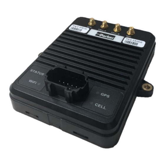
About the PVSG-IQAN (Parker Vehicle System Gateway with IQAN Integration) 1.3. Hardware Overview Figure 2: PVSG-IQAN-C2E1M2W1U1 1.3.1. Plug & Play Hardware ▪ Fully provisioned, multi-country capable SIM ▪ 4G LTE cellular, Wi-Fi, ▪ 2 CAN networks -250kbps (IQAN CAN Protocol, SAE J1939 Protocol, other possible) ▪... -
Page 15: Ordering Part Numbers & Accessories
OTA capabilities for the duration defined in the description. Premium, Standard and Basic service levels are explained in the table below. It is recommended that the Parker antenna part numbers 167019 or 167021 are used for optimum performance. -
Page 16: Parker Mobile Iot Part Numbers
About the PVSG-IQAN (Parker Vehicle System Gateway with IQAN Integration) 1.4.1. Parker Mobile IOT Part Numbers Parker IOT Description Basic Standard Premium Service Service Options Service contract period Service Plans Americas: 4G LTE B2, B4, B5, B12 166032 167792 167793... -
Page 17: Service Notes
Representative for more information. ▪ Customers who sell Parker’s mobile IoT solution must have a signed SaaS (Software as a Service) agreement in place. In addition, the customer must have created a EULA (End User License Agreement) and process for flow down to end users ▪... -
Page 18: Quick Start Guide
2.1. Getting Started using the Web Application for Remote Monitoring The PVSG-IQAN gateway pairs with the Parker Mobile IoT cloud to enable several IoT services. This section is meant as a quick start to create your assets entity in the cloud. -
Page 19: Requisite Information
Quick Start Guide 2.1.1. Requisite Information You must have the following information available to create your asset in the Parker Mobile IoT cloud. • Login information for the users • The gateway’s Master Tag (M-Tag) ID • The gateway’s Master Tag ID assigned to your IQAN Connect organization. -
Page 20: Parker Mobile Iot , Users, Assets, Organizations
Quick Start Guide 2.1.2. Parker Mobile IoT , Users, Assets, Organizations. First the user must log into the web portal with their credentials. To get access credentials contact your account administrator, an email/username and password will be sent to your email inbox to create a new user account. - Page 21 After the user has logged into their organization, they will be greeted with their fleet overview page. Figure 4. IQAN Connect Fleet overview page. In order to start using the Parker Mobile IoT portal, an account administrator should create organizations, users and assets.
- Page 22 2.1.2.1. Create New users A user is created and assigned a specific role in an organization. This step by step instructions shows how to create a new user in the system and grant access to Parker Mobile IoT 2.0 portal.
- Page 23 Quick Start Guide Figure 6. Create New Users Steps.
- Page 24 Quick Start Guide 2.1.2.2. Create new Assets Create new assets by “pairing” the machines or assets with a gateway. Administrators can create and manage the assets on the fleet from the asset page. The asset page lists all assets that belong to the selected organizations in the Org Selector. 1.
- Page 25 Quick Start Guide 2.1.2.3. Create Organizations or Customer Accounts Administrator will have access to create new organization or accounts. Organizations are grouped in a hierarchical order. A “parent” organization is created by an administrator, and that “parent” organization can hold many “children” organizations. 1.
- Page 26 Quick Start Guide Figure 8. Create New Organizations Steps.
-
Page 27: Getting Started With Remote Monitoring And Diagnostics With Iqan System
Accessories) 2.2.1. Requirements • PVSG-IQAN gateway • Cellular Coverage • Parker Mobile IoT Service Plan subscription • Gateway installed per Section 3 of the guide • Gateway connected to diagnostic bus of the IQAN system Before starting your remote connection, ensure the gateway is powered up and the status... -
Page 28: Iqan Application Requirements
Quick Start Guide 2.2.2. IQAN Application Requirements The PVSG-IQAN modem support IQANdesign version 5.03 or newer versions. Note for more detailed instructions on the requirements for the IQAN application please reference the help files within the IQAN Design software or the IQAN web forum. IQAN User Forum Link: https://forum.iqan.se The gateway module must be added to the IQAN application before remote diagnostics can... -
Page 29: Remotely Connecting To Your Iqan System
Quick Start Guide The security section of the IQAN application must also be updated before remote diagnostics can be performed. Under the security properties there are 3 options that must be setup. Figure 10. IQAN Design security settings for remote connectivity. The security permissions are modifiable by an OEM or integrator;... - Page 30 Quick Start Guide blinking green status light. There is no activation required, the system will connect immediately. Danger! Risk of death or injury. Ensure that the vehicle is in a safe state before performing remote diagnostics or program updates. The user can remotely connect with both IQANdesign and IQANrun. Once running IQANdesign and IQANrun, select Communication from the top dropdown menu and select Connect Remote to open the Connect via Internet window.
- Page 31 Figure 11. IQAN MD4-7 System info page. To gather the key through the web application, first log into the web application as noted in section 2.1.2. 2.1.2. Parker Mobile IoT , Users, Assets, Organizations Assuming the user has admin privileges, follow these steps: 1.
- Page 32 Quick Start Guide Figure 12 . Location of IQAN Connect Key in web application. Once the user has the system key, they can enter it in IQANdesign or IQANrun by selecting the add button in the Connect via Internet window. This window will now show the Master Tag or Machine ID and if the asset is online or offline every time you access it.
- Page 33 Quick Start Guide user with popup windows or status bars. For example, the system will notify a user with a popup when there is a successful connection. Figure 14. Connection established confirmation Once the system confirms connection, the user can use any of the diagnostic tools as if they were plugged directly into the back of the module.
-
Page 34: Connecting With Iqango App
Quick Start Guide 2.2.4. Connecting with IQANgo App After the PVSG-IQAN gateway has been installed, per section 3 and 4 of this manual, the system is ready to connect. The user must next make sure the vehicle is on, power is supplied to the system and the gateway is connected to the IQANconnect servers with the blinking green status light. -
Page 35: Mounting The Pvsg-Iqan To A Vehicle
Mounting the PVSG-IQAN to a Vehicle 3. Mounting the PVSG-IQAN to a Vehicle The original equipment manufacturer (OEM) or integrator must ensure the product is securely mounted to the vehicle. For best results it is recommended that the gateway is mounted inside the cab of the vehicle, inside the front dash panel. -
Page 36: Dimensions
Mounting the PVSG-IQAN to a Vehicle 3.1. Dimensions The PVSG-IQAN dimensions are shown in Figure 12 below. 1.28’’ / 3.25cm 1.70’’ / 4.31cm 5.84’’ / 14.83cm 5.25’’ / 13.33cm 4.70’’ / 11.93cm 6.30’’ / 16.00cm 1.70’’ / 4.31cm Figure 15 : PVSG-IQAN dimensions... -
Page 37: Designing And Connecting The Vehicle Harness
Mounting the PVSG-IQAN to a Vehicle 3.2. Designing and Connecting the Vehicle Harness The vehicle manufacturer or integrator is responsible for designing a vehicle harness that mates with the PVSG-IQAN connector(s). The vehicle harness design depends on the following: ▪ How the user’s inputs, outputs, communication, and power pins are configured. -
Page 38: Gateway Connections (Pinout)
Gateway Connections (Pinout) 4. Gateway Connections (Pinout) 4.1. Power and Vehicle Communication 4.1.1. Mating Connector The mating connector for the PVSG-IQAN is a Deutsch DT16, key A. Figure 13: Mating connector Mating Connector Part Numbers Connector Housing Terminals Plugs (empty positions) Main DT16-18SA-K004 1062-16-0644... -
Page 39: Pinout
Gateway Connections (Pinout) 4.1.2. Pinout The following tables shows the pin-outs for the connectors: Main Connector Pin-out Function Ethernet TXN Ethernet TXP Ethernet RXN Ethernet RXP Battery Negative (-) Module Unswitched Battery (+) Module CAN0/CANA - High CAN0/CANA - Low CAN1/CANB –... -
Page 40: Canbus Module Block Diagram
Gateway Connections (Pinout) 4.1.3. CANBUS Module Block Diagram When utilizing the PVSG-IQAN gateway with an IQAN based control system, it is very important to connect the diagnostic bus of the gateway to the diagnostic bus of the IQAN Master Controller. See Figure 15. IQAN Master IQAN Master Controller... -
Page 41: Antenna Connections
Gateway Connections (Pinout) 4.2. Antenna Connections Figure 17: PVSG-IQAN antenna connections Antenna Connectors Type Function GPS (left) Cell-D (Diversity – LTE 2) Cell-M (Main – LTE 1) RP-SMA Wi-Fi (right) Damage to equipment! SMA connections should be torqued between 7 and 10 in-lbs (0.8 –1.1N) to avoid damage. -
Page 42: Power
Power 5. Power The PVSG-IQAN is powered by a direct battery connection. The gateway is turned on by applying power to the power control input. The PVSG-IQAN operates in a 12 V or 24 V system and can operate from 6.5 V up to 32 V with over-voltage protection at 36 V. -
Page 43: Power Control Input
Power Control Input 6. Power Control Input The PVSG-IQAN has 1 power control input. The power control input activates the unit or shuts it down. Damage to equipment! Do not connect inputs directly to unprotected inductive loads such as solenoids or relay coils, as these can produce high voltage spikes that may damage the PVSG-IQAN. -
Page 44: Power Control Input Connections
Power Control Input 6.1.1. Power Control input connections You must be aware of the following when connecting the power control digital input: ▪ The power control digital input is usually connected to the vehicle ignition, but it can be connected to any power source in a system. ▪... -
Page 45: Communication
Communication 7. Communication The types of communication available to the PVSG-IQAN are Controller Area Network (CAN), Ethernet, Modem (GSM), Wi-Fi, and USB host/device. 7.1. Controller Area Network The PVSG-IQAN has 2 CAN communication ports available. The hardware provides controller area network (CAN) communication according to the SAE J1939 specification, making the PVSG-IQAN compatible with CAN- based protocol through software. -
Page 46: J1939 Can Installation Connections
Communication 7.1.2. J1939 CAN Installation Connections The CAN connection for the PVSG-IQAN should conform to the J1939 standard. The SAE J1939 standard is a robust automotive specification that is a good CAN installation guideline even when the J1939 CAN protocol is not being used. For a list of J1939 connection considerations, refer to the SAE J1939 specifications available through the Society for Automotive Engineers. - Page 47 Communication Note: Ground loops can damage electronic modules. The CAN Shield can only be grounded to one point on the network. If grounded to multiple points, a ground loop may occur. ▪ CAN Stubs: The CAN stubs cannot be longer than 1 meter, and each stub should vary in length to eliminate bus reflections and ensure proper idle state voltage levels.
-
Page 48: Modem And Cellular Communications
7.2.1. Modem Specifications The main specifications of the PVSG-IQAN cellular modems interface are listed in the following table: 7.2.1.1. North America/ Central / South America Cellular interface Americas PVSG-IQAN-C2E1M2W1U1 Parameter Description Bands 12 (700MHz), 5 (850MHz), 4 (1700MHz), & 2... - Page 49 Communication 7.2.1.2. Europe/Australia/New Zealand/other International locations Cellular interface Europe/Australia/New Zeeland PVSG-IQAN-C2E1M3W1U1 Parameter Description 4G LTE Bands 20 (800MHz), 3 (1800MHz), & 7 (2600MHz) 3GPP Release 9 Cat 1: up to 10.3 Mb/s downlink, up to 5.2 Mb/s uplink 2G GSM/GPRS/EDGE: 900/1800 Mhz 3GPP Release 9 GPRS: Class 33, CS1-4 –...
-
Page 50: Sim Carrier Information
Communication 7.2.2. SIM Carrier Information The PVSG-IQAN comes supplied with a SIM card provisioned for AT&T and their partner’s global networks. Figure 18 provides a list of countries where the PVSG- IQAN could have service available. Note: for countries in group B, may require additional approval and country certifications. -
Page 51: Wi-Fi
Communication 7.3. Wi-Fi The PVSG-IQAN gateway will support the following Wi-Fi Services in the Premium and Basic service plans: Figure 21: Gateway countries of operation • IQAN WiFi Diagnostics: Connect mobile devices (PC, phone, tablet) to gateway access point, perform IQAN real time diagnostic and software OTA updates •... - Page 52 Communication The main specifications of the PVSG-IQAN Wi-Fi interface are listed in the following table: (Note 1: Certain governments do not permit operating with all available channels.) Wi-Fi interface Parameter Description Standard 802.11 b/g/n (2.4GHz) Channels (see note 1) 1-13 Operational modes APN, Client, Concurrent (two simultaneous instances)
-
Page 53: Gps/Gnss Interface
Communication 7.4. GPS/GNSS Interface The PVSG-IQAN has an onboard GPS chip for calculating geolocation information to be used throughout the cloud application. Note: Table below shows theoretical best performances of hardware, many variables including weather, clear view from antenna to sky, number of signals on template, etc. impact performance. -
Page 54: Troubleshooting
Troubleshooting 8. Troubleshooting 8.1. Status LEDs The PVSG-IQAN has 4 status LEDs for displaying operational modes and for troubleshooting. Figure22: Location of LEDs The messages displayed by the LEDs are listed in the following tables: Status LED Pattern Description Red solid Indicates error (also read during programming) Blue heartbeat Gateway booting, in process of establishing connection... -
Page 55: Troubleshooting
Troubleshooting GPS LED Pattern Description Red solid Indicates error (also red during programming) Red Slow Blink Gateway booting, in process of booting GPS firmware Blinking Yellow GPS firmware booted. Searching for Satellites Cellular LED Red solid Indicates error (also red during programming) Red Slow Blink Software booting or no sim card installed Yellow blink... -
Page 56: Iqan Connect Remote Diagnostics Will Not Connect
Troubleshooting 8.2.2. IQAN Connect remote diagnostics will not connect. • Check to see if the status light has a green heartbeat blink. It typically takes 1-2 minutes for the gateway to connect to the IQAN Connect diagnostic servers. • Ensure the gateway is connected to the cellular network and has IP connectivity. The cellular status light should be solid green. -
Page 57: Users Gateway Will Not Show Its Gps Location
8.2.5. After reading this manual, the user is still having issues, where can they get help? Contact the supplier of the PVSG-IQAN gateway or open a ticket with the Parker Support Desk 1-888-915-4357 (help) number when looking for assistance on any of the IoT Help product and services. - Page 58 Troubleshooting Parker Support Desk Site: https://parkeriot.atlassian.net/servicedesk Support Help Desk information and instructions https://parkeriot.atlassian.net/servicedesk/customer/portal/4/topic/6346dba5-089d- 4686-b76f-d5220d5971d9/article/862912513...
-
Page 59: Markings/Approvals
Markings/Approvals 9. Markings/Approvals The PVSG-IQAN meets the following regulations. 9.1. ISO Standards/Certifications CISPR 25 Method, 30 - 1000MHz, ISO 13766 Limits, FCC CFR Radiated Emissions 47 Part 15B, Class A; ICES-003 ISO 11452-4 (BCI), 20 - 200MHz at 100mA Conducted Immunity ISO 11452-2 (ALSE), 200MHz-2000MHz 1kHz AM 80% at Radiated immunity 200V/m;... -
Page 60: Fcc Compliance - Na Gateway
Markings/Approvals Climate -40C 4 hours; +85C 4 hours Storage Temperature -40C to +70C, 98% RH, 24-hour cycle, 10 days Combined Environment -40C to +85C, 5 min dwell, 200 cycles Air-to-Air Thermal Shock Ingress Protection ISO 20653, IP6K7 Solar Radiation SAE J2527, Xenon Weatherometer, 210 hours IEC 60068-2-52, Test Kb, Severity Level 3 Salt Spray Brake Fluid, Gasoline, Diesel Fuel, Isopropyl Alcohol,... -
Page 61: Ic Compliance - Na Gateway
Markings/Approvals 9.3. IC Compliance – NA Gateway This device complies with Industry Canada license-exempt RSS standard(s). Operation is subject to the following two conditions: (1) this device may not cause harmful interference, and (2) this device must accept any interference received, including interference that may cause undesired operation. -
Page 62: Eu Declaration Of Conformity - Na Gateway
Markings/Approvals 9.4. EU Declaration of conformity – NA Gateway... - Page 63 Markings/Approvals...
-
Page 64: Eu Declaration Of Conformity - Eu Gateway
Markings/Approvals 9.5. EU Declaration of conformity – EU Gateway... - Page 65 Markings/Approvals...
-
Page 66: Appendix
Appendix 10. Appendix... -
Page 67: Diagram Conventions
Appendix 10.1. Diagram conventions The following symbols are used in the schematic diagrams in this document:... - Page 68 Appendix Symbol Meaning General input General output Frequency input Analog input Frequency sensor Pulse sensor Resistive sensor General sensor Application switch Load Pull-down resistor Pull-up resistor...
- Page 69 Appendix Symbol Meaning Battery Fuse Resistor Ground Chassis ground...
- Page 70 HY33-5027-IB/US...
Need help?
Do you have a question about the PVSG-IQAN-C2E1M2W1U1 and is the answer not in the manual?
Questions and answers