
Related Manuals for Parker PSVG-IQAN-C2E1M1W1U1


Summary of Contents for Parker PSVG-IQAN-C2E1M1W1U1
- Page 1 Parker Vehicle System Gateway for Mobile Equipment with IQAN Integration PSVG-IQAN-C2E1M1W1U1 U s e r G u i d e U G - P V S G - I Q A N - C 2 E 1 M 1 W 1 U 1 - 1 0 1 7 - 0 0 1...
- Page 2 Offer of Sale The items described in this document are hereby offered for sale by Parker Hannifin Corporation, its subsidiaries or its authorized distributors. This offer and its acceptance are governed by the provisions stated in the "Offer of...
-
Page 3: Table Of Contents
Safety during installation ......................... vii Safety during start-up ........................viii Safety during maintenance and fault diagnosis ................viii 1. About the PVSG-IQAN (Parker Vehicle System Gateway with IQAN Integration) ..1 1.1. Remote Monitoring Capabilities ....................1 1.2. Diagnostic Troubleshooting Capabilities ................... 2 1.3. - Page 4 8.2.5. After reading this manual, the user is still having issues, where can they get help? . 31 9. Markings/Approvals ...................... 32 9.1. FCC Compliance ........................32 9.2. IC Compliance ......................... 33 9.3. EU Declaration of conformity ....................34 10. Environmental specifications ..................36 11. Appendix ........................37 11.1. Diagram conventions ......................37 PSVG-IQAN-C2E1M1W1U1...
-
Page 5: Publication History
Publication History The following table provides an overview of the changes made to this document over the course of its publication history. Release Date Description of Change Rev 001 – 5-18-2018 First release of this document Rev 002 – 6-18-2018 Updated URL’s, Added System Block Diagram, added carrier information, added metric units User Guide... -
Page 6: Safety
Contact the manufacturer if there is anything you are not sure about or if you have any questions regarding the product and its handling or maintenance. The term "manufacturer" refers to Parker Hannifin Corporation. Safety symbols The following symbols are used in this document to indicate potentially... -
Page 7: Welding After Installation
Safety Do not use the product if electronic modules, cabling, or connectors are damaged or if the control system shows error functions. Electronic control systems in an inappropriate installation and in combination with strong electromagnetic interference fields can, in extreme cases, cause an unintentional change of speed of the output function. -
Page 8: Safety During Start-Up
Before performing any work on the hydraulics control electronics, ensure that The machine cannot start moving. Functions are positioned safely. The machine is turned off. The hydraulic system is relieved from any pressure. Supply voltage to the control electronics is disconnected. viii PSVG-IQAN-C2E1M1W1U1... -
Page 9: About The Pvsg-Iqan (Parker Vehicle System Gateway With Iqan Integration)
PVSG-IQAN-C2E1M1W1U1. The product offers IQAN remote diagnostics and remote monitoring capabilities. 1.1. Remote Monitoring Capabilities By pairing with Parker’s Voice of the Machine cloud, the end to end solution also has a number of remote monitoring capabilities. ... -
Page 10: Diagnostic Troubleshooting Capabilities
About the PVSG-IQAN (Parker Vehicle System Gateway with IQAN Integration) 1.2. Diagnostic Troubleshooting Capabilities Using the remote IQAN Connect diagnostic tools allows a user to remotely connect to a vehicle enabling the following functionality over the air: View live vehicle data for trouble-shooting issues ... -
Page 11: Hardware Overview
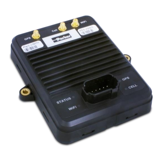
About the PVSG-IQAN (Parker Vehicle System Gateway with IQAN Integration) 1.3. Hardware Overview Figure 1: PVSG-IQAN-C2E1M1W1U1 The main features of the PVSG-IQAN hardware are listed in the following table: PVSG-IQAN-C2E1M1W1U1 Characteristic Description Status LEDs 4 x tri-color Communication CAN x 2... -
Page 12: Ordering Part Numbers
1.4. Ordering Part Numbers The PVSG-IQAN gateway includes one part number all-inclusive of cellular service, web portal service and IQAN Connect service for the duration defined in the description. It is recommended that the Parker antenna is used for optimum performance. Part Number... -
Page 13: Quick Start Guide
Quick Start Guide 2. Quick Start Guide 2.1. Getting Started using the Web Application for Remote Monitoring The PVSG-IQAN gateway pairs with the Voice of the Machine™ cloud to enable a number of IoT services. This section is meant as a quick start to create your assets entity in the cloud. -
Page 14: Logging In And Creating The Asset
After the user has logged into their organization they will be greeted with their fleet overview page. The user must click the (+) button in the low right hand corner to initiate the creation of the asset. Figure 3. IQAN Connect Fleet overview page. PSVG-IQAN-C2E1M1W1U1... - Page 15 Quick Start Guide A modal will appear as shown in Figure 9 below where you fill in the identifying details and define which signals will be captured from the vehicle. Figure 4. IQAN Connect asset creation modal. The Master Tag field provides a searchable drop down list populated with all of the Master Tags you have in your organization.
-
Page 16: Getting Started With Remote Monitoring And Diagnostics With An Iqan System
The PVSG-IQAN modem is in IQAN Design version 5.03+. Note for more detailed instructions on the requirements for the IQAN application please reference the help files within the IQAN Design software or the IQAN web forum. IQAN User Forum Link: https://forum.iqan.se PSVG-IQAN-C2E1M1W1U1... - Page 17 Quick Start Guide The gateway module must be added to the IQAN application before remote diagnostics can be performed and connected to the diagnostic bus. Select the GT gateway using the add button in the IQAN system layout canvas. The modem is listed under Gateway Modules.
-
Page 18: Remotely Connecting To Your Iqan System
This can be found in the system menu of the IQAN module. For example on an MD4-7 the key is displayed in the System Info page. Select Main Menu then System and finally Info. The key can also be used as a system information channel and displayed elsewhere in the program. PSVG-IQAN-C2E1M1W1U1... - Page 19 Quick Start Guide Figure 7. IQAN MD4-7 System info page. Once the user has the system key, they can enter it in IQAN Design or IQAN Run by selecting the add button in the Connect via Internet window. This window will now show the Master Tag or Machine ID and if the asset is online or offline every time you access it.
- Page 20 Quick Start Guide Figure 9. Connection established confirmation Once the system confirms connection, the user can use any of the diagnostic tools as if they were plugged directly into the back of the module. PSVG-IQAN-C2E1M1W1U1...
-
Page 21: Mounting The Pvsg-Iqan To A Vehicle
Mounting the PVSG-IQAN to a Vehicle 3. Mounting the PVSG-IQAN to a Vehicle It is up to the original equipment manufacturer (OEM) or integrator to ensure the product is securely mounted to the vehicle. For best results it is recommended that the gateway is mounted inside the cab of the vehicle. -
Page 22: Dimensions
Mounting the PVSG-IQAN to a Vehicle 3.1. Dimensions The PVSG-IQAN dimensions are shown in Figure 10 below. 5.84” 5.84 (148.5 mm) 5.25” 5.25 (133.5 mm) 4.69” 4.69 (119 mm) 6.30” 6.30 (160 mm) 1.61” 1.61 (41.0 mm) Figure 10: PVSG-IQAN dimensions PSVG-IQAN-C2E1M1W1U1... -
Page 23: Designing And Connecting The Vehicle Harness
Mounting the PVSG-IQAN to a Vehicle 3.2. Designing and Connecting the Vehicle Harness The vehicle manufacturer or integrator is responsible for designing a vehicle harness that mates with the PVSG-IQAN connector(s). The vehicle harness design depends on the following: How the users's inputs, outputs, communication, and power pins are configured. -
Page 24: Gateway Connections (Pinout)
CAN communication channels. In addition, to the Deutsch connector there are 3 antenna connectors. Damage to Equipment! The technician installing the connector should ensure that the connector is inserted in the correct orientation as power applied to unprotected pins can cause permanent damage to the gateway. PSVG-IQAN-C2E1M1W1U1... -
Page 25: Pinout
Gateway Connections (Pinout) 4.1.2. Pinout The following tables shows the pin-outs for the connectors: Figure 12: PVSG-IQAN connector Main Connector Pin-out Function Not used in IQAN Connect Solution Not used in IQAN Connect Solution Not used in IQAN Connect Solution Not used in IQAN Connect Solution Ground (Negative battery) +VBATT (Positive battery) -
Page 26: Canbus Module Block Diagram
When utilizing the PVSG-IQAN gateway with an IQAN based control system, it is very important to connect the diagnostic bus of the gateway to the diagnostic bus of the IQAN Master Controller. See Figure 13. Figure 13. Block diagram of wiring PVSG-IQAN Gateway PSVG-IQAN-C2E1M1W1U1... -
Page 27: Antenna Connections
Gateway Connections (Pinout) 4.2. Antenna Connections Figure 14: PVSG-IQAN antenna connections Antenna Connectors Type Function GPS (left) GSM (center) RP-SMA Wi-Fi (right) User Guide... -
Page 28: Power
85% efficiency for step-down regulators, and peak cellular current during a 1-slot Tx burst at maximum power. Note the burst duration is typically 1 ms or less, thus not affecting recommended fuse ratings. PSVG-IQAN-C2E1M1W1U1... -
Page 29: Power Control Input
Power Control Input 6. Power Control Input The PVSG-IQAN has 1 power control input. The power control input activates the unit or shuts it down. Damage to equipment! Do not connect inputs directly to unprotected inductive loads such as solenoids or relay coils, as these can produce high voltage spikes that may damage the PVSG-IQAN. -
Page 30: Power Control Input Connections
PVSG-IQAN will deactivate. The following shows a typical power control digital input connection: Internal to product Application Switch Power Control Input Power Control Fuse Min. Pull-Down 200 mA Resistor Battery Figure 15: Power control digital input installation connections PSVG-IQAN-C2E1M1W1U1... -
Page 31: Communication
Communication 7. Communication The types of communication available to the PVSG-IQAN are Controller Area Network (CAN), Ethernet, Modem (GSM), Wi-Fi, and USB host/device. 7.1. Controller Area Network The PVSG-IQAN has 2 CAN communication ports available. The hardware provides controller area network (CAN) communication according to the SAE J1939 specification, making the PVSG-IQAN compatible with CAN-based protocol through software. -
Page 32: J1939 Can Installation Connections
CAN network. This cable cannot be longer than 40 meters and must have a 120 Ω terminating resistor at each end. The 120 Ω terminating resistors eliminate bus reflections and ensure proper idle-state voltage levels. PSVG-IQAN-C2E1M1W1U1... - Page 33 Communication The CAN cable is very susceptible to system noise; therefore, CAN shield must be connected as follows: a. Connect CAN Shield to the point of least electrical noise on the CAN bus. b. Connect CAN Shield as close to the center of the CAN bus as possible.
-
Page 34: Modem And Cellular Communications
HTTP/FTP/SSL Supported antenna External SMA connector Certifications Aeris, AT&T, PTCRB (Carrier) US (FCC CFR 47 part 15) Canada (IC RSS) 7.2.2. Carrier Information The PVSG-IQAN comes supplied with a SIM card provisioned for AT&T and their partner’s global networks. PSVG-IQAN-C2E1M1W1U1... -
Page 35: Wifi
Communication 7.3. WiFi Note: user interface for configuring the WiFi client is not currently supported in the off the shelf version of PVSG-IQAN software. This section is for reference only and subject to change with subsequent releases. The main specifications of the PVSG-IQAN WiFi interface are listed in the following table: WiFi interface Parameter... -
Page 36: Troubleshooting
Indicates error (also read during programing) Blue heartbeat Gateway booting, in process of establishing connection Red heartbeat Gateway software running, logging data, connection to IQAN Connect servers in process. Green Heartbeat Gateway has IP connectivity and is connected to IQAN Connect diagnositc servers. PSVG-IQAN-C2E1M1W1U1... -
Page 37: Troubleshooting
Troubleshooting GPS LED Pattern Description Red solid Indicates error (also red during programing) Red Slow Blink Gateway booting, in process of booting GPS firmware Blinking Yellow GPS firmware booted. Searching for Satellites Cellular LED Red solid Indicates error (also red during programming) Red Slow Blink Software booting or no sim card installed Yellow blink... -
Page 38: Iqan Connect Remote Diagnostics Will Not Connect
CANBUS, none of the signals will transmit until that last signal is seen by the gateway logger. For more information on configuring a template in the IQAN Connect cloud interface the user should check the template knowledge base. PSVG-IQAN-C2E1M1W1U1... -
Page 39: Users Gateway Will Not Show Its Gps Location
Troubleshooting 8.2.4. Users gateway will not show its GPS location. If the GPS LED is a slow red blink: Wait 1 minute for device to boot. Power cycle the gateway. If the GPS LED is a yellow blink Wait for 3 minutes for the firmware to fully initialize. -
Page 40: Markings/Approvals
20cm from all persons and must not be co-located or operating in conjunction with any other antenna or transmitter except in accordance with FCC’s multi-transmitter policy. This device may contain one or more of the following FCC compliant modules: Contains FCC ID: ORR-HEDW131 Contains FCC ID: XPYLISAU230 PSVG-IQAN-C2E1M1W1U1... -
Page 41: Ic Compliance
Markings/Approvals 9.2. IC Compliance This device complies with Industry Canada license-exempt RSS standard(s). Operation is subject to the following two conditions: (1) this device may not cause harmful interference, and (2) this device must accept any interference received, including interference that may cause undesired operation. -
Page 42: Eu Declaration Of Conformity
Markings/Approvals 9.3. EU Declaration of conformity PSVG-IQAN-C2E1M1W1U1... - Page 43 Markings/Approvals User Guide...
-
Page 44: Environmental Specifications
Environmental specifications 10. Environmental specifications The following specifications apply to the PVSG-IQAN. IP Rating: IP67 Operating Temperature: -40°C to 70°C 1 Storage Temperature: -40°C to 85°C PSVG-IQAN-C2E1M1W1U1... -
Page 45: Appendix
Appendix 11. Appendix 11.1. Diagram conventions The following symbols are used in the schematic diagrams in this document: Symbol Meaning General input General output Frequency input Analog input Frequency sensor Pulse sensor Resistive sensor General sensor User Guide... - Page 46 Appendix Symbol Meaning Application switch Load Pull-down resistor Pull-up resistor Battery Fuse Resistor Ground Chassis ground PSVG-IQAN-C2E1M1W1U1...
- Page 48 HY33-5027-IB/US...
Need help?
Do you have a question about the PSVG-IQAN-C2E1M1W1U1 and is the answer not in the manual?
Questions and answers