
Related Manuals for Parker PVSG


Summary of Contents for Parker PVSG
- Page 1 Effective: June 2019 Supersedes: UG-PVSG-1051000-201906-003 PVSG User Guide Parker Vehicle System Gateway...
- Page 2 Parker Hannifin Canada Electronic Controls Division 1305 Clarence Avenue Winnipeg, MB R3T 1T4 Canada office +1 204 452 6776 Fax +1 204 478 1749 http://www.parker.com/ecd Copyright 2019 © Parker Hannifin Corporation. All rights reserved. No part of this work may be reproduced, published, or distributed in any form or by any means (electronically, mechanically, photocopying, recording, or otherwise), or stored in a database retrieval system, without the prior written permission of Parker Hannifin Corporation in each instance. Warning! FAILURE OR IMPROPER SELECTION OR IMPROPER USE OF THE PRODUCTS AND/OR SYSTEMS DESCRIBED HEREIN OR RELATED ITEMS CAN CAUSE DEATH, PERSONAL INJURY AND PROPERTY DAMAGE. • • This•document•and•other•information•from•Parker•Hannifin•Corporation,•its•subsidiaries•and• authorized•distributors•provide•product•and/or•system•options•for•further•investigation•by•users• having•technical•expertise. • • The•user,•through•its•own•analysis•and•testing,•is•solely•responsible•for•making•the•final•selection• of•the•system•and•components•and•assuring•that•all•performance,•endurance,•maintenance,• safety•and•warning•requirements•of•the•application•are•met.•The•user•must•analyze•all•aspects• of•the•application,•follow•applicable•industry•standards,•and•follow•the•information•concerning• the•product•in•the•current•product•catalog•and•in•any•other•materials•provided•from•Parker•or•its• subsidiaries•or•authorized•distributors. • • To•the•extent•that•Parker•or•its•subsidiaries•or•authorized•distributors•provide•component•or• system•options•based•upon•data•or•specifications•provided•by•the•user,•the•user•is•responsible•for• determining•that•such•data•and•specifications•are•suitable•and•sufficient•for•all•applications•and• reasonably•foreseeable•uses•of•the•components•or•systems. • •...
-
Page 3: Table Of Contents
Safety•symbols•............................VI General•safety•regulations•........................VI Welding•after•installation• ........................VII Construction•regulations•........................VII Safety•during•installation•........................VII Safety•during•start-up• .......................... VII Safety•during•maintenance•and•fault•diagnosis• ................VII About the PVSG ........................ 1 Connectors and pin-outs ....................3 Inputs ..........................6 3.1.• Input•capabilities• ........................6 3.1.1.• Power•control•digital•input•connections•................7 3.1.2.• Active-high•digital•input•connections•..................7 Outputs ..........................9 4.1.•... - Page 4 PVSG User Guide...
-
Page 5: Publication History
Publication History The•following•table•provides•an•overview•of•the•changes•made•to•this•document•over•the•course•of•its• publication•history. Release Date Description of Change Rev. 001 First release of this document Rev. 002 Realignment to match platform changes. Minor edits throughout. 01/07/2019 Rev. 003 Add note for USB no communication, 6/12/2019 • PVSG User Guide... -
Page 6: Safety
The•term•“manufacturer”•refers•to•Parker•Hannifin•Corporation. Safety symbols The•following•symbols•are•used•in•this•document•to•indicate•potentially•hazardous•situations: Danger! Risk of death or injury. Warning! Risk of damage to equipment or degradation of signal When•you•see•these•symbols,•follow•the•instructions•carefully•and•proceed•with•caution. General safety regulations Work•on•the•hydraulics•control•electronics•may•only•be•carried•out•by•trained•personnel•who•are•well- acquainted•with•the•control•system,•the•machine,•and•its•safety•regulations. •Follow•the•manufacturer’s•regulations•when•mounting,•modifying,•repairing,•and• maintaining•equipment.•The•manufacturer•assumes•no•responsibility•for•any•accidents• caused•by•incorrectly•mounted•or•incorrectly•maintained•equipment.•The•manufacturer• assumes•no•responsibility•for•the•system•being•incorrectly•applied,•or•the•system•being• programmed•in•a•manner•that•jeopardizes•safety. • •Do•not•use•the•product•if•electronic•modules,•cabling,•or•connectors• are•damaged•or•if•the•control•system•shows•error•functions. ••Electronic•control•systems•in•an•inappropriate•installation•and•in•combination•with• strong•electromagnetic•interference•fields•can,•in•extreme•cases,•cause•an•unintentional• change•of•speed•of•the•output•function. PVSG User Guide... -
Page 7: Welding After Installation
Safety during start-up Danger! Risk of death or injury. Do•not•start•the•machine’s•engine•before•the•control• system•is•mounted•and•its•electrical•functions•have•been•verified.• • Do•not•start•the•machine•if•anyone•is•near•the•machine. Safety during maintenance and fault diagnosis Before•performing•any•work•on•the•hydraulics•control•electronics,•ensure•that • • The•machine•cannot•start•moving. • • Functions•are•positioned•safely. • • The•machine•is•turned•off. • • The•hydraulic•system•is•relieved•from•any•pressure. • • Supply•voltage•to•the•control•electronics•is•disconnected. • PVSG User Guide... -
Page 8: About The Pvsg
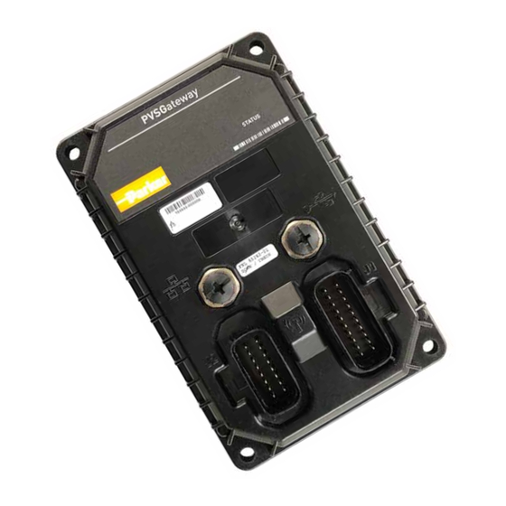
1. About the PVSG The•PVSG•(Parker•Vehicle•System•Gateway)•product•is•a•gateway•providing•routing•and•gateway• interfacing•between•various•communication•ports.•The•hardware•includes•the•following•interfaces•for• use•in•a•system•environment: • • 5x•CAN•(depending•on•version) • • 4x•LIN•(depending•on•version) • • 1x•J1708•(depending•on•version) • • 1x•USB•(OTG) • • 1x•Ethernet•100baseTx•(depending•on•version) • • 1x•802.11•b,g,n• • • 1x•external•wireless•antenna•(depending•on•version) • • 2x•digital•inputs•(depending•on•version) • • 1x•high-side•output•(depending•on•version) • Figure 1.1. PVSG module • The•design•of•the•gateway•platform•is•structured•to•provide•two•levels•of•connectivity.••Packages•of• software•capability•supported•by•each•version•is•included•with•the•gateway.•It•is•also•possible•to•provide•... - Page 9 Ethernet 100base Tx for wired PC connection USB Host/Device (OTG) J1708 Legacy heavy-duty vehicle (truck and bus) protocol For communication with automotive components Data logging memory Memory for logging events, CAN messages etc. Real time clock Inputs Active-high GPIO with wake up capability Outputs High-side Advanced Characteristic Number Description CAN bus ports Supports CAN 2.0 for e.g. J1939, CANopen WiFi 802.11 b,g,n External antenna conn. Antenna may be connected for additional range Ethernet 100base Tx for wired PC connection USB Host/Device (OTG) J1708 Legacy heavy-duty vehicle (truck and bus) protocol For communication with automotive components Data logging memory 4 GB Memory for logging events, CAN messages etc. Real time clock Inputs Active-high GPIO with wake up capability Outputs High-side PVSG User Guide...
-
Page 10: Connectors And Pin-Outs
Contacts 330013004 (16-20 awg gold) 330013004 (16-20 awg gold) The•pins•in•the•Molex•MX150•connectors•are•used•for•power,•input,•output,•CAN,•LIN,•and•J1708• communication•channels,•depending•on•version. The•following•tables•shows•the•pin-outs•for•the•MX150•connectors: J1 Connector Pinout I/O Name Function INPUT2 Input2 (GPIO) INPUT1 Input1 (GPIO) CAN2_SHLD CAN2 Shield CAN2_L CAN2 Low CAN2_H CAN2 High CAN1_SHLD CAN1 Shield CAN1_L CAN1 Low CAN1_H CAN1 High GND (Negative battery) +VBATT +VBATT (Positive battery) CAN3_SHLD CAN3 Shield CAN3_H CAN3 High CAN3_L CAN3 Low PVSG User Guide... - Page 11 CAN5 High CAN5_L CAN5 Low GND (Negative battery) J2 Connector Pinout I/O Name Function J1708A CAN_L J1708B GND (Negative battery) LIN2 LIN2 GND (Negative battery) LIN1 LIN1 Reserved OUTPUT1 Output1 Reserved GND (Negative battery) LIN4 LIN4 Reserved Reserved Reserved GND (Negative battery) LIN3 LIN3 In•addition,•there•is•1•x•USB•(M12•5•pin),•and•depending•on•configuration,•1x•Ethernet•(M12•4•pin)•and•1• x•SMA•Wi-Fi•antenna•connector. • Figure 2.2. M12 connector example PVSG User Guide...
- Page 12 Possible mating part number J11 connector, 3M: 3N104-D000-S08 BF 4-pin, code D J12 connector, AMP: 4-2271112-1 5-pin, code B •The•following•tables•shows•the•pin-outs•for•the•M12•connectors: J11 Connector Pinout I/O Name Function Ethernet_TX+ Ethernet Transmit+ Ethernet_RX+ Ethernet Receive+ Ethernet_TX- Ethernet Transmit- Ethernet_RX- Ethernet Receive- J12 Connector Pinout I/O Name Function USB GND USB PWR USB D+ USB D- USB_OTG USB OTG ID • PVSG User Guide...
-
Page 13: Inputs
Damage to equipment!•Do•not•connect•inputs•directly•to•unprotected•inductive•loads• such•as•solenoids•or•relay•coils,•as•these•can•produce•high•voltage•spikes•that•may• damage•the•CM0504.•If•an•inductive•load•must•be•connected•to•an•input,•use•a•protective• diode•or•transorb. 3.1. Input capabilities There•are•2•active•high•inputs•(INPUT1•and•INPUT2).•This•GPIO•Type•1•input••provides•a•fixed•input• detection•threshold•with•fixed•pull•down•resistance. The•primary•function•of•the•inputs•is•to•provide•a•wake•on•ignition•feature•as•a•digital•input.•The•‘Wake• Up’•functionality•is•software•configurable. A•secondary•function•is•to•interface•with•switch•sensors•in•an•application. The•following•table•provides•specifications•for•the•inputs: GPIO input Type 1 characteristics Item Unit Input voltage range (non-operational) Over voltage Pull-up resistance open Input resistance w.r.t. ground 10.11 kΩ Negative going threshold 3.375 3.67 Positive going threshold 3.65 3.931 Filtering - hardware time constant PVSG User Guide... -
Page 14: Power Control Digital Input Connections
Internal to product Application Switch Power Control Input Power Control Pull-Down Resistor Battery Figure 3.1. Power control digital input installation connections 3.1.2. Active-high digital input connections A•digital•input•is•typically•connected•to•a•switch•that•is•either•open•or•closed. • • When•an•active-high•switch•is•open,•the•pull-down•resistor•ensures•that•no•voltage•exists•on•the• input•signal,•which•will•be•interpreted•by•the•PVSG•as•inactive. • • When•the•switch•is•closed,•the•input•is•connected•to•battery•voltage,•which•will•be•interpreted•by•the• PVSG•as•active. For•an•input•that•is•active-high • • It•must•be•connected•to•battery•power•so•that•there•is•a•battery•connection•when•the•state•of•the• input•changes. • • The•power•provided•to•the•digital•switch•connected•to•the•input•must•be•provided•through•a•fuse•in• the•wire•harness. PVSG User Guide... - Page 15 The•following•diagram•shows•a•typical•active-high•digital•input•connection: • Internal to product Application Switch Active High Digital Input Battery Figure 3.2. Active-high digital input installation connections PVSG User Guide...
-
Page 16: Outputs
V/us Output pin capacitance 4.2. High-side output connection When•connecting•the•high-side•output,•note•that• • • High-side•output•circuitry•is•connected•internally•to•battery•power•(VBATT). • • High-side•output•can•provide•switched•battery•power•to•any•load•type•in•a•vehicle. • • High-side•output•can•source•up•to•0.25•A•max. • • High-side•output•have•internal•flyback•diodes,•which•are•needed•when•driving•inductive•loads•(the• flyback•diodes•absorb•electrical•energy•when•the•load•is•turned•off ).• Inductive•loads•will•create•an•average•current•flow•that•moves•out•of•the•high-side•output.•When•the• output•is•on,•the•current•flows•through•the•output•driver,•and•when•the•output•is•off,•the•current•flows• through•the•flyback•diode.•A•duty•cycle•of•50%•will•produce•the•worst•case•average•current•flow•through• these•two•devices. Note:•If•large•inductive•loads•are•used,•and•the•high-side•output•is•providing•a•continuous•PWM•signal,• the•PWM•peak•current•must•not•be•greater•than•the•specified•continuous•current•for•the•output•(in• continuous•mode,•the•average•current•flow•through•the•diode•at•50%•duty•cycle•is•approximately•equal•to• ½•the•peak•current). When•connecting•high-side•outputs,•ensure•you•follow•these•best•practices: • • High-side•outputs•should•not•be•connected•to•loads•that•will•draw•currents•greater•than•the• maximum•peak•current,•or•maximum•continuous•current. • • The•grounds•for•the•loads•should•be•connected•physically•close•to•the•PVSG•power•grounds. PVSG User Guide... - Page 17 The•following•shows•a•typical•high-side•output•connection: • Internal to product High-Side Output Application Load Figure 4.1. High-side output installation connections PVSG User Guide...
-
Page 18: Power
5. Power The•PVSG•is•powered•by•a•direct•battery•connection.•The•gateway•is•turned•on•by•applying•power•to•a• power•control•input•or•a•CAN•message•depending•on•configuration.• The•PVSG•in•a•12•V•or•24•V•system•and•can•operate•from•6.5•V•up•to•32•V•with•over-voltage•protection•at• 36•V. The•following•table•provides•specifications•for•the•PVSG•power: Item Unit Input voltage for normal operation Maximum continuous voltage Maximum peak current Current draw in sleep mode Recommended External Fuse PVSG User Guide... -
Page 19: Communication
Wake•on•CAN•provides•a•low-current•sleep•mode•that•turns•on•the•PVSG•when•a•CAN•message•is• received•by•the•module. It•is•not•possible•to•filter•messages•that•are•used•to•turn•on•the•PVSG•using•Wake•on•CAN.•For•this•reason,• any•message•will•turn•on•the•PVSG.•The•application•software•must•be•written•to•determine•how•the•PVSG• will•behave•when•it•is•turned•on. The•following•table•provides•specifications•for•the•CAN: Item Unit Baud rate limitations (hardware) 1000 kbps Baud rate limitations (software) 1000 kbps Wake on CAN current draw Termination resistor Ω 6.1.2. J1939 CAN Installation Connections The•CAN•connection•for•the•PVSG•should•conform•to•the•J1939•standard.•The•J1939•standard•is•a•robust• automotive•specification•that•is•a•good•CAN•installation•guideline•even•when•the•J1939•CAN•protocol•is• not•being•used. For•a•list•of•J1939•connection•considerations,•refer•to•the•SAE•J1939•specifications•available•through•the• Society•for•Automotive•Engineers.•SAE•J1939-11•covers•the•physical•aspects•of•the•CAN•bus•including• cable•type,•connector•type,•and•cable•lengths. Note:•The•standard•variant•of•the•PVSG•does•not•have•a•CAN•termination•resistor,•which•is•based•on•the• assumption•that•the•CAN•bus•is•terminated•in•the•harness. The•following•lists•the•elements•that•are•required•for•a•J1939•CAN•connection: • • CAN•Cable:•A•shielded•twisted-pair•cable•should•be•used•when•connecting•multiple•modules•to• the•CAN•bus.•The•cable•for•the•J1939•CAN•bus•has•three•wires:•CAN•High,•CAN•Low,•and•CAN• Shield•(which•connect•to•the•corresponding•CAN_HIGH,•CAN_LOW,•and•CAN_SHIELD•pins•on•the• PVSG User Guide... - Page 20 • • CAN•Stubs:•The•CAN•stubs•cannot•be•longer•than•1•meter,•and•each•stub•should•vary•in•length•to• eliminate•bus•reflections•and•ensure•proper•idle•state•voltage•levels. • • Max•Number•of•Modules•in•a•System:•The•CAN•bus•can•handle•a•maximum•of•30•modules•in•a• system•at•one•time. The•following•shows•a•typical•CAN•connection•using•the•SAE•J1939•standard: • CAN Network Backbone (less than 40 meters long) T connectors 120 ohm 120 ohm Terminator Terminator Variable length Node Node Node CAN stub (<1m) Node Node Figure 6.1. J1939 CAN connection PVSG User Guide...
-
Page 21: Wi-Fi
Compliance with FCC/IC (wireless) This•device•complies•with•Part•15•of•the•FCC•Rules.•Operation•is•subject•to•the•following•two•conditions: 1.• This•device•may•not•cause•harmful•interference,•and 2.• This•device•must•accept•any•interference•received,•including•interference•that•may•cause•undesired• operation. This•digital•apparatus•meets•all•requirements•of•the•Canadian•Interference-Causing•Equipment• Regulations.•Wireless•operation•is•subject•to•2•conditions.•The•first•is•that•the•wireless•device•may•not• cause•interference.•The•second•is•that•the•wireless•device•must•accept•any•interference,•including• interference•that•may•cause•undesired•operation•of•the•device. Warning! Exposure to Radio Frequency Radiation!•The•radiated•output•power•of•this• device•is•below•the•FCC•radio•frequency•exposure•limits.•Nevertheless,•the•device•should• be•used•in•such•a•manner•that•the•potential•for•human•contact•is•minimized•during•normal• operation.•During•normal•operation:•To•avoid•the•possibility•of•exceeding•the•FCC•radio• frequency•exposure•limits,•human•proximity•to•the•antenna•should•not•be•less•than•5•cm•(2• inches)•if•integrated•into•the•unit. Contact•the•manufacturer•if•there•is•anything•you•are•not•sure•about•or•if•you•have•any•questions• regarding•the•product•and•its•handling•or•maintenance.• The•term•“manufacturer”•refers•to•Parker•Hannifin•Corporation. 6.3. USB The•PVSG•gateway•supports•one•USB•port•capable•of•full•speed•USB•2.0.••The•unit•supports•OTG,•which• means•the•port•has•a•5th•pin.•The•USB•port•is•configured•as•Host•or•Device•based•on•connection•of•the•ID• pin.• • • Connect•to•USB•Ground•=•Host • • Leave•Unconnected•=•Device PVSG User Guide... -
Page 22: Sae J1708
VBUS output current limit VBUS output current rating ESD suppression, data pins 0.25 ESD suppression, ID pin Reverse standoff voltage (see note 1) Note 1:••USB•connectors•are•not•rated•to•survive•a•short•to•vehicle•battery. Note:•If•the•USB•from•the•PVSG•is•plugged•into•the•PC•and•doesn’t•work.••Try•unplugging•the• USB•cable,•power•cycle•the•PVSG,•then•plug•the•USB•cable•back•in.••Repeat•until•the•USB•is• successfully•connected. 6.4. SAE J1708 SAE•J1708•is•a•legacy•standard•used•for•serial•communications•between•ECUs•on•a•heavy•duty•vehicle• and•also•between•a•computer•and•the•vehicle.•The•PVSG•can•has•1•of•this•type•communication•port. The•J1708•port•is•provided•to•connect•J1939•networks•to•legacy•J1708•protocol•devices. Note: On•power•up•the•PVSG•J1708•communication•port•is•briefly•held•dominant.•The•PVSG• J1708•communication•port•is•also•briefly•held•dominant•while•PVSG•prepares•to•go•to•sleep,• and•while•it•is•being•reprogrammed.•While•the•PVSG•J1708•communication•port•is•dominant,• message•transmission•is•not•possible•on•the•J1708•communication•bus•connected•to•the• PVSG. 6.5. Local Interconnect Network The•LIN•(Local•Interconnect•Network)•protocol•is•a•compliment•to•the•CAN•protocol•and•may•be•used•for• applications•that•are•not•time•critical•or•do•not•need•extreme•fault•tolerance.• The•PVSG•may•have•up•to•4•LIN•ports•depending•on•configuration. As•a•cost-effective•network•solution,•LIN•is•mainly•used•for•less•critical•functions,•and•implementing•low• cost•automotive•sensors.•LIN•is•not•quite•as•robust•as•the•CAN•protocol.• 6.6. Ethernet The•PVSG•has•up•to•1•Ethernet•port•depending•on•version.•The•port•meets•standard•IEEE•802.3,• 10/100BaseTx•and•has•a•transmission•rate•of•10/100•Mbits•per•second. PVSG User Guide... - Page 23 PVSG User Guide...
-
Page 24: Installation
7. Installation Because•every•system•is•different,•it•is•not•feasible•to•provide•detailed•installation•instructions•that•will•be• suitable•for•every•assembly.•This•chapter•therefore•provides•only•high-level•guidelines•on•installing•the• PVSG. The•vehicle•manufacturer•is•responsible•for•creating•procedures•for•mounting•the•CM0504•in• a•vehicle•during•production•assembly. 7.1. Mounting the PVSG to a Vehicle It•is•up•to•the•original•equipment•manufacturer•(OEM)•to•ensure•the•product•is•securely•mounted•to•the• vehicle. The•following•guidelines•are•related•to•physically•attaching•the•PVSG•to•a•vehicle: • • Secure•the•PVSG•with•bolts•in•all•bolt•holes•using•Hex•Head•1/4”-20•or•equivalent•metric•size•(M6)• bolts. • • The•bolts•should•be•tightened•according•to•the•recommended•installation•torque•of•2.5•Nm•(22•in- lbs). 7.2. Mechanical Requirements Review•the•following•mechanical•requirements•before•selecting•a•mounting•location•for•the•PVSG: • • The•PVSG•should•be•mounted•vertically•so•moisture•will•drain•away•from•it.• • • The•wire•harness•should•have•drip•loops•incorporated•into•the•design•to•divert•water•away•from•the• PVSG. • • The•harness•should•be•shielded•from•harsh•impact. • •... -
Page 25: Dimensions
7.3. Dimensions The•following•shows•the•dimensions•of•the•PVSG•in•millimeters: Figure 7.1. PVSG dimensions PVSG User Guide... - Page 26 © 2019 Parker Hannifin Corporation. All rights reserved. MSG33-5026-IB/US 06/12/2019 Parker Hannifin Canada Electronic Controls Division 1305 Clarence Avenue Winnipeg, MB, R3T 1T4 Canada phone 204 452 6776 fax 204 478 1749 www.parker.com/ecd Your Local Authorized Parker Distributor...
Need help?
Do you have a question about the PVSG and is the answer not in the manual?
Questions and answers