Table of Contents
Advertisement
Quick Links
Advertisement
Table of Contents
Troubleshooting

Related Manuals for Parker PSVG-IQAN-C2E1M2W1U1


Summary of Contents for Parker PSVG-IQAN-C2E1M2W1U1
- Page 1 Parker Gateway for Mobile IoT Solution PSVG-IQAN-C2E1M2W1U1 U s e r G u i d e...
- Page 2 Offer of Sale The items described in this document are hereby offered for sale by Parker Hannifin Corporation, its subsidiaries or its authorized distributors. This offer and its acceptance are governed by the provisions stated in the "Offer of...
-
Page 3: Table Of Contents
Safety during installation ........................ viii Safety during start-up ........................ix Safety during maintenance and fault diagnosis ................ix 1. About the PVSG-IQAN (Parker Vehicle System Gateway with IQAN Integration) ..1 1.1. Remote Monitoring Capabilities ....................1 1.2. Diagnostic Troubleshooting Capabilities ................... 2 1.3. - Page 4 8.2.5. After reading this manual, the user is still having issues, where can they get help? . 36 9. Markings/Approvals ...................... 37 9.1. ISO Standards/Certifications ....................37 9.2. FCC Compliance ........................38 9.3. IC Compliance ......................... 39 9.4. EU Declaration of conformity ....................40 10. Appendix ........................42 10.1. Diagram conventions ......................43 PSVG-IQAN-C2E1M2W1U1...
-
Page 5: Publication History
Publication History The following table provides an overview of the changes made to this document over the course of its publication history. Release Date Description of Change Rev 001 – 5-18-2018 First release of this document Rev 002 – 6-18-2018 Updated URL’s, Added System Block Diagram, added carrier information, added metric units Rev 003 –... -
Page 6: Safety
Contact the manufacturer if there is anything you are not sure about or if you have any questions regarding the product and its handling or maintenance. The term "manufacturer" refers to Parker Hannifin Corporation. Safety symbols The following symbols are used in this document to indicate potentially... -
Page 7: General Safety Regulations
Safety General safety regulations Work on the hydraulics control electronics may only be carried out by trained personnel who are well-acquainted with the control system, the machine, and its safety regulations. Follow the manufacturer's regulations when mounting, modifying, repairing, and maintaining equipment. The manufacturer assumes no responsibility for any accidents caused by incorrectly mounted or incorrectly maintained equipment. -
Page 8: Welding After Installation
Safety during installation Incorrectly positioned or mounted cabling can be influenced by radio signals, which can interfere with the functions of the system. viii PSVG-IQAN-C2E1M2W1U1... -
Page 9: Safety During Start-Up
Safety Safety during start-up Danger! Risk of death or injury. Do not start the machine's engine before the control system is mounted and its electrical functions have been verified. Do not start the machine if anyone is near the machine. Safety during maintenance and fault diagnosis Before performing any work on the hydraulics control electronics, ensure that... -
Page 11: About The Pvsg-Iqan (Parker Vehicle System Gateway With Iqan Integration)
PVSG-IQAN-C2E1M2W1U1. The product offers IQAN remote diagnostics and remote monitoring capabilities. 1.1. Remote Monitoring Capabilities By pairing with Parker’s Voice of the Machine cloud, the end to end solution also has a number of remote monitoring capabilities. ▪... -
Page 12: Diagnostic Troubleshooting Capabilities
About the PVSG-IQAN (Parker Vehicle System Gateway with IQAN Integration) 1.2. Diagnostic Troubleshooting Capabilities Using the remote IQAN Connect diagnostic tools allows a user to remotely connect to a vehicle enabling the following functionality over the air: ▪ View live vehicle data for trouble-shooting issues ▪... -
Page 13: Hardware Overview
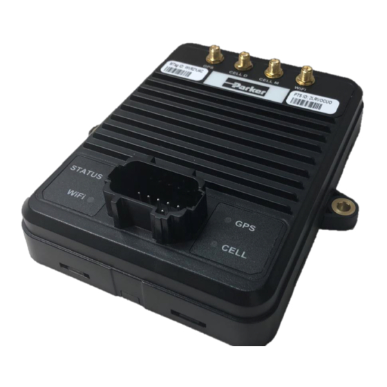
About the PVSG-IQAN (Parker Vehicle System Gateway with IQAN Integration) 1.3. Hardware Overview Figure 1: PVSG-IQAN-C2E1M2W1U1 The main features of the PVSG-IQAN hardware are listed in the following table: PVSG-IQAN-C2E1M2W1U1 Characteristic Description Status LEDs 4 x tri-color Communication CAN x 2... -
Page 14: Ordering Part Numbers & Accessories
1.4. Ordering Part Numbers & Accessories The PVSG-IQAN gateway includes one part number all-inclusive of cellular service, web portal service and IQAN Connect service for the duration defined in the description. It is recommended that the Parker antenna is used for optimum performance. Part Number... -
Page 15: Quick Start Guide
Quick Start Guide 2. Quick Start Guide 2.1. Getting Started using the Web Application for Remote Monitoring The PVSG-IQAN gateway pairs with the Voice of the Machine™ cloud to enable a number of IoT services. This section is meant as a quick start to create your assets entity in the cloud. -
Page 16: Logging In And Creating The Asset
After the user has logged into their organization they will be greeted with their fleet overview page. The user must click the (+) button in the low right hand corner to initiate the creation of the asset. PSVG-IQAN-C2E1M2W1U1 Figure 3. IQAN Connect Fleet overview page. - Page 17 Quick Start Guide A modal will appear as shown in Figure 9 below where you fill in the identifying details and define which signals will be captured from the vehicle. Figure 4. IQAN Connect asset creation modal. • The Master Tag field provides a searchable drop down list populated with all of the Master Tags you have in your organization.
-
Page 18: Getting Started With Remote Monitoring And Diagnostics With An Iqan System
Gateway installed per Section 3 of the guide • Gateway connected to diagnostic bus of the IQAN system Before starting your remote connection, ensure the gateway is powered up and the status light is blinking green, indicating the gateway is connected to the IQAN Connect servers. PSVG-IQAN-C2E1M2W1U1... -
Page 19: Iqan Application Requirements
Quick Start Guide 2.2.2. IQAN Application Requirements The PVSG-IQAN modem is in IQAN Design version 5.03+. Note for more detailed instructions on the requirements for the IQAN application please reference the help files within the IQAN Design software or the IQAN web forum. -
Page 20: Remotely Connecting To Your Iqan System
Connect servers with the blinking green status light. There is no activation required, the system will connect immediately. Danger! Risk of death or injury. Ensure that the vehicle is in a safe state before performing remote diagnostics or program updates. PSVG-IQAN-C2E1M2W1U1... - Page 21 Quick Start Guide The user can remotely connect with both IQAN Design and IQAN Run. Once running IQAN Run or design, select Communication from the top dropdown menu and select Connect Remote to open the Connect via Internet window. You must have IQAN Connect licenses to use this service.
- Page 22 Connect via Internet window. This window will now show the Master Tag or Machine ID and if the asset is online or offline every time you access it. An example of the window is shown in Figure 4, note Master tag I1GDENN is online. PSVG-IQAN-C2E1M2W1U1...
- Page 23 Quick Start Guide Figure 9. IQAN Design remote connectivity. The user choses the asset they would like to connect to and clicks the connect button. While performing the update the system handshakes and communicates the status to the user with pop up windows or status bars. For example, the system will notify a user with a popup when there is a successful connection.
-
Page 24: Mounting The Pvsg-Iqan To A Vehicle
The following guidelines are related to physically attaching the PVSG- IQAN to a vehicle: ▪ Secure the PVSG-IQAN with bolts in all bolt holes using Hex Head #10 or equivalent metric size (M5) bolts. ▪ Torque recommendation of 25-35 in-lbf (2.8 – 4 N-m) PSVG-IQAN-C2E1M2W1U1... -
Page 25: Dimensions
Mounting the PVSG-IQAN to a Vehicle 3.1. Dimensions The PVSG-IQAN dimensions are shown in Figure 10 below. 5.84” (148.5 mm) 5.25” (133.5 mm) 4.69” (119 mm) 6.30” (160 mm) 1.61” (41.0 mm) Figure 11: PVSG-IQAN dimensions... -
Page 26: Designing And Connecting The Vehicle Harness
IQAN simply by clicking the mating connectors into the connector ports on the PVSG-IQAN. Damage to Equipment! The technician installing the connector should take special care that the connector is inserted in the correct orientation as power applied to unprotected pins can cause permanent damage to the gateway. PSVG-IQAN-C2E1M2W1U1... -
Page 27: Gateway Connections (Pinout)
Gateway Connections (Pinout) 4. Gateway Connections (Pinout) 4.1. Power and Vehicle Communication 4.1.1. Mating Connector The mating connector for the PVSG-IQAN is a Deutsch DT16, key A. Figure 12: Mating connector Mating Connector Part Numbers Connector Housing Terminals Plugs (empty positions) Main DT16-18SA-K004 1062-16-0644... -
Page 28: Pinout
Not used in IQAN Connect Solution The pins with italicized descriptions are not used in the IQAN Connect solution. It is recommended to plug the un used pins for the connector. The pins with bold descriptions are required for the device to boot. PSVG-IQAN-C2E1M2W1U1... -
Page 29: Canbus Module Block Diagram
Gateway Connections (Pinout) 4.1.3. CANBUS Module Block Diagram When utilizing the PVSG-IQAN gateway with an IQAN based control system, it is very important to connect the diagnostic bus of the gateway to the diagnostic bus of the IQAN Master Controller. See Figure 13. Figure 14. -
Page 30: Antenna Connections
GPS (left) Cell-D (Diversity – LTE 2) Cell-M (Main – LTE 1) RP-SMA Wi-Fi (right) Damage to equipment! SMA connections should be torqued between 7 and 10 in-lbs (0.8 –1.1N) to avoid damage. Connectors are not repairable if damaged. PSVG-IQAN-C2E1M2W1U1... -
Page 31: Power
Power 5. Power The PVSG-IQAN is powered by a direct battery connection. The gateway is turned on by applying power to the power control input. The PVSG-IQAN operates in a 12 V or 24 V system and can operate from 6.5 V up to 32 V with over-voltage protection at 36 V. -
Page 32: Power Control Input
The power control digital input activates the PVSG-IQAN when switched high, and begin a controlled shutdown sequence (if applicable) and de- activates the module when power is removed. It is recommended that this input be controlled by the vehicle ignition switch. PSVG-IQAN-C2E1M2W1U1... -
Page 33: Power Control Input Connections
Power Control Input The following table provides specifications for the power control digital input: Power Control Digital Input Specifications Item Unit Input voltage range Ω Input resistance 110k Maximum voltage 6.1.1. Power Control input connections You must be aware of the following when connecting the power control digital input: ▪... - Page 34 Power Control Input The following shows a typical power control digital input connection: Internal to product Application Switch Power Control Input Power Control Fuse Min. Pull-Down 200 mA Resistor Battery Figure 16: Power control digital input installation connections PSVG-IQAN-C2E1M2W1U1...
-
Page 35: Communication
Communication 7. Communication The types of communication available to the PVSG-IQAN are Controller Area Network (CAN), Ethernet, Modem (GSM), Wi-Fi, and USB host/device. 7.1. Controller Area Network The PVSG-IQAN has 2 CAN communication ports available. The hardware provides controller area network (CAN) communication according to the SAE J1939 specification, making the PVSG-IQAN compatible with CAN-based protocol through software. -
Page 36: J1939 Can Installation Connections
SAE J1939-11 covers the physical aspects of the CAN bus including cable type, connector type, and cable lengths. Note: The standard variant of the PVSG-IQAN does not have a CAN termination resistor, which is based on the assumption that the CAN bus is terminated in the harness. PSVG-IQAN-C2E1M2W1U1... - Page 37 Communication The following lists the elements that are required for a J1939 CAN connection: ▪ CAN Cable: A shielded twisted-pair cable should be used when connecting multiple modules to the CAN bus. The cable for the J1939 CAN bus has three wires: CAN - High, CAN - Low, and CAN Shield (which connect to the corresponding CAN_HIGH, CAN_LOW, and CAN_SHIELD pins on the connector).
- Page 38 The following shows a typical CAN connection using the SAE J1939 standard: CAN Network Backbone (less than 40 meters long) T connectors 120 ohm 120 ohm Terminator Terminator Variable length Node Node Node CAN stub (<1m) Node Node Figure 17: J1939 CAN connection PSVG-IQAN-C2E1M2W1U1...
-
Page 39: Modem And Cellular Communications
Communication 7.2. Modem and Cellular Communications 7.2.1. Modem Specifications The main specifications of the PVSG-IQAN cellular modem interface are listed in the following table: Cellular interface Parameter Description Bands 12 (700MHz), 5 (850MHz), 4 (1700MHz), & 2 4G LTE (1900MHz) 3GPP Release 9 Cat 1: up to 10.3 Mb/s downlink, up to 5.2 Mb/s uplink 850/900/1900/2100 MHz... -
Page 40: Wifi
WPA (TKIP, AES) WPA2 (CCMP, AES) WAPI hardware support 64/128 bit AES hardware support Supported antenna External RP-SMA connector Certifications US (FCC CFR 47 part 15) Canada (IC RSS) Note 1: Certain governments do not permit operating with all available channels. PSVG-IQAN-C2E1M2W1U1... -
Page 41: Gps/Gnss Interface
Communication 7.4. GPS/GNSS Interface The PVSG-IQAN has an onboard GPS chip for calculating geolocation information to be used throughout the cloud application. Note: Table below shows theoretical best performances of hardware, many variables including weather, clear view from antenna to sky, number of signals on template, etc impact performance. -
Page 42: Troubleshooting
Indicates error (also read during programing) Blue heartbeat Gateway booting, in process of establishing connection Red heartbeat Gateway software running, logging data, connection to IQAN Connect servers in process. Green Heartbeat Gateway has IP connectivity and is connected to IQAN Connect diagnositc servers. PSVG-IQAN-C2E1M2W1U1... -
Page 43: Troubleshooting
Troubleshooting GPS LED Pattern Description Red solid Indicates error (also red during programing) Red Slow Blink Gateway booting, in process of booting GPS firmware Blinking Yellow GPS firmware booted. Searching for Satellites Cellular LED Red solid Indicates error (also red during programming) Red Slow Blink Software booting or no sim card installed Yellow blink... -
Page 44: Iqan Connect Remote Diagnostics Will Not Connect
CANBUS, none of the signals will transmit until that last signal is seen by the gateway logger. For more information on configuring a template in the IQAN Connect cloud interface the user should check the template knowledge base. PSVG-IQAN-C2E1M2W1U1... -
Page 45: Users Gateway Will Not Show Its Gps Location
Troubleshooting 8.2.4. Users gateway will not show its GPS location. • If the GPS LED is a slow red blink: Wait 1 minute for device to boot. Power cycle the gateway. • If the GPS LED is a yellow blink Wait for 3 minutes for the firmware to fully initialize. -
Page 46: After Reading This Manual, The User Is Still Having Issues, Where Can They Get Help
8.2.5. After reading this manual, the user is still having issues, where can they get help? Contact the supplier of the PVSG-IQAN gateway or open a ticket with the IQAN Connect help desk. Parker Mobile IoT Knowledge Base Link: https://parkeriot.atlassian.net/wiki/x/RoJ6E PSVG-IQAN-C2E1M2W1U1... -
Page 47: Markings/Approvals
Markings/Approvals 9. Markings/Approvals The PSVG-IQAN meets the following regulations. 9.1. ISO Standards/Certifications CISPR 25 Method, 30 - 1000MHz, ISO 13766 Limits, Radiated Emissions FCC CFR 47 Part 15B, Class A; ICES-003 ISO 11452-4 (BCI), 20 - 200MHz at 100mA Conducted Immunity ISO 11452-2 (ALSE), 200MHz-2000MHz 1kHz AM 80% Radiated immunity at 200V/m;... -
Page 48: Fcc Compliance
20cm from all persons and must not be co-located or operating in conjunction with any other antenna or transmitter except in accordance with FCC’s multi-transmitter policy. This device may contain one or more of the following FCC compliant modules: ▪ Contains FCC ID: ORR-HEDW131 ▪ Contains FCC ID: XPY1EHM44NN PSVG-IQAN-C2E1M2W1U1... -
Page 49: Ic Compliance
Markings/Approvals 9.3. IC Compliance This device complies with Industry Canada license-exempt RSS standard(s). Operation is subject to the following two conditions: (1) this device may not cause harmful interference, and (2) this device must accept any interference received, including interference that may cause undesired operation. -
Page 50: Eu Declaration Of Conformity
Markings/Approvals 9.4. EU Declaration of conformity PSVG-IQAN-C2E1M2W1U1... - Page 51 Markings/Approvals...
-
Page 52: Appendix
Appendix 10. Appendix PSVG-IQAN-C2E1M2W1U1... -
Page 53: Diagram Conventions
Appendix 10.1. Diagram conventions The following symbols are used in the schematic diagrams in this document: Symbol Meaning General input General output Frequency input Analog input Frequency sensor Pulse sensor Resistive sensor General sensor Application switch Load... - Page 54 Appendix Symbol Meaning Pull-down resistor Pull-up resistor Battery Fuse Resistor Ground Chassis ground PSVG-IQAN-C2E1M2W1U1...
- Page 56 HY33-5027-IB/US...
Need help?
Do you have a question about the PSVG-IQAN-C2E1M2W1U1 and is the answer not in the manual?
Questions and answers