Table of Contents

Related Manuals for Fronius KD 1500 D-11


Summary of Contents for Fronius KD 1500 D-11
- Page 1 Perfect Welding / Perfect Charging / / Solar Energy Operating Instructions KD 1500 D-11 Wire-feed unit 42,0426,0033,EN 006-14052020 Fronius prints on elemental chlorine free paper (ECF) sourced from certified sustainable forests (FSC).
- Page 3 Thank you for the trust you have placed in our company and congratulations on buying this high-quality Fronius product. These instructions will help you familiarise yourself with the product. Reading the instructions carefully will enable you to learn about the many different features it has to offer.
-
Page 5: Table Of Contents
Contents Safety rules ..............................General ..............................Proper use ............................Environmental conditions........................Obligations of the operator........................Obligations of personnel ........................Mains connection ..........................Protecting yourself and others ......................Noise emission values .......................... Danger from toxic gases and vapours ....................Danger from flying sparks ........................Risks from mains current and welding current.................. - Page 6 Care, maintenance and disposal ....................... General ..............................Every start-up............................Every 6 months ............................. Disposal ..............................Technical data............................KD 1500 D-11 ............................
-
Page 7: Safety Rules
Safety rules General The device is manufactured using state-of-the-art technology and according to recognised safety standards. If used incorrectly or misused, however, it can cause: injury or death to the operator or a third party, damage to the device and other material assets belonging to the operating company, inefficient operation of the device. -
Page 8: Obligations Of The Operator
Ambient temperature range: during operation: -10 °C to + 40 °C (14 °F to 104 °F) during transport and storage: -20 °C to +55 °C (-4 °F to 131 °F) Relative humidity: up to 50% at 40 °C (104 °F) up to 90% at 20 °C (68 °F) The surrounding air must be free from dust, acids, corrosive gases or substances, etc. -
Page 9: Noise Emission Values
Suitable protective clothing must be worn when working with the device. The protective clothing must have the following properties: Flame-resistant Insulating and dry Covers the whole body, is undamaged and in good condition Safety helmet Trousers with no turn-ups Protective clothing refers to a variety of different items. Operators should: Protect eyes and face from UV rays, heat and sparks using a protective visor and reg- ulation filter Wear regulation protective goggles with side protection behind the protective visor... -
Page 10: Danger From Flying Sparks
The following components are responsible, amongst other things, for the degree of toxicity of welding fumes: Metals used for the workpiece Electrodes Coatings Cleaners, degreasers, etc. Welding process used The relevant material safety data sheets and manufacturer's specifications for the listed components should therefore be studied carefully. -
Page 11: Meandering Welding Currents
The electrode (rod electrode, tungsten electrode, welding wire, etc.) must never be immersed in liquid for cooling Never touch the electrode when the power source is switched on. Double the open circuit voltage of a power source can occur between the welding elec- trodes of two power sources. -
Page 12: Emc Device Classifications
EMC Device Clas- Devices in emission class A: sifications Are only designed for use in industrial settings Can cause line-bound and radiated interference in other areas Devices in emission class B: Satisfy the emissions criteria for residential and industrial areas. This is also true for residential areas in which the energy is supplied from the public low-voltage mains. -
Page 13: Specific Hazards
Specific hazards Keep hands, hair, clothing and tools away from moving parts. For example: Fans Cogs Rollers Shafts Wirespools and welding wires Do not reach into the rotating cogs of the wire drive or into rotating drive components. Covers and side panels may only be opened/removed while maintenance or repair work is being carried out. -
Page 14: Requirement For The Shielding Gas
Odourless and colourless shielding gas may escape unnoticed if an adapter is used for the shielding gas connection. Prior to assembly, seal the device-side thread of the adapter for the shielding gas connection using suitable Teflon tape. Requirement for Especially with ring lines, contaminated shielding gas can cause damage to equipment and the shielding gas reduce welding quality. -
Page 15: Safety Measures At The Installation Location And During Transport
Safety measures A device toppling over could easily kill someone. Place the device on a solid, level surface at the installation such that it remains stable location and dur- The maximum permissible tilt angle is 10°. ing transport Special regulations apply in rooms at risk of fire or explosion Observe relevant national and international regulations. -
Page 16: Commissioning, Maintenance And Repair
Cooling Liquid FCL 10/20 does not ignite. The ethanol-based coolant can ignite under cer- tain conditions. Transport the coolant only in its original, sealed containers and keep well away from any sources of ignition. Used coolant must be disposed of properly in accordance with the relevant national and international regulations. -
Page 17: Data Protection
Fronius International GmbH hereby declares that the device is compliant with Directive 2014/53/EU. The full text on the EU Declaration of Conformity can be found at the following address: http://www.fronius.com Devices marked with the CSA test mark satisfy the requirements of the relevant standards for Canada and the USA. -
Page 18: General
MagicWave 2200 / 2500 / 3000 Job MagicWave 4000 / 5000 Job Application area The KD 1500 D-11 robot wirefeeder has been designed to be mounted on the robot arm. The cold wire feeder is suitable for all standard shielding gases. Warning notices The wire-feed unit has safety symbols on the rating plate. - Page 19 Welding is dangerous. The following basic requirements must be met to en- sure the equipment is used properly: Welders must be sufficiently qualified Suitable protective equipment must be used All persons not involved must be kept at a safe distance from the wire- feed unit and the welding process Do not use the functions described here until you have fully read and under- stood the following documents:...
-
Page 20: Controls, Connections And Mechanical Components
Controls, connections and mechanical components General NOTE! Due to firmware or software updates, you may find that your device has certain func- tions that are not described in these operating instructions or vice versa. Certain illustrations may also differ slightly from the actual controls on your device, but these controls function in exactly the same way. -
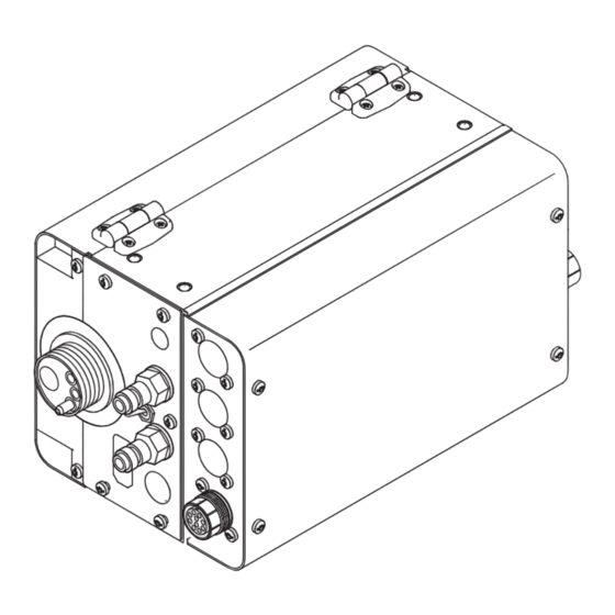
Page 21: Cold Wire Feeder Rear
Hold the button for up to one second ... Irrespective of what value has been set, the wirefeed speed remains at 1 m/min or 39.37 ipm for the first second. Hold the button for up to 2.5 seconds ... After one second, the wirefeed speed increases at a uniform rate over the next 1.5 seconds. - Page 22 Item Designation (17) Wire infeed tube (18) Blanking cover (19) Shielding gas connection (20) Water return connection (red) (21) Water flow connection (blue)
-
Page 23: Connect The Cold Wire Feeder To The Power Source
Connect the cold wire feeder to the power source General The cold wire feeder is connected to the power source using the interconnecting hosepack. NOTE! Risk of damage to the wirefeeding hose if it is attached to the hosepack. Do not attach the wirefeeding hose to the hosepack under any circumstances. Connect the cold WARNING! wire feeder to the... - Page 24 Plug gas hose (4) from gas cylinder pressure regulator into shielding gas connection IMPORTANT! If a CrashBox is fitted, insert control plug (2) into the socket provided on the welding torch. Attach the colour-coded water return (blue) and water flow (red) hoses of the intercon- necting hosepack to the appropriate connections (5) and (7) Tighten union nuts on water feed and return hoses...
-
Page 25: Fitting The Welding Torch
Fitting the welding torch Fit the welding torch (10) (11) (12) turn the power source mains switch to the "O" position If present: connect colour-coded external water connections for water flow (11) and return (7) Plug welding potential bayonet plug into current socket (4) and turn to fasten it Insert the wirefeed, infeed tube first, into the wirefeeding connection (3) Tighten the union nut by hand to fix in place... -
Page 26: Inserting/Replacing Feed Rollers
Inserting/replacing feed rollers General In order to achieve the best welding wire feed, the feed rollers must be suitable for the di- ameter and alloy of the wire being welded. IMPORTANT! Use only feed rollers that are suitable for the welding wire in question. An overview of the feed rollers available and their potential application areas can be found in the spare parts lists. -
Page 27: Feeding In The Welding Wire
Feeding in the welding wire Feeding in the CAUTION! welding wire Risk of injury from the spring effect of the coiled welding wire. While inserting the welding wire into the 4 roller drive, hold the end of the wire firmly to avoid injuries caused by the wire springing back. -
Page 28: Set The Contact Pressure
Set the contact pressure NOTE! Set the contact pressure in such a way that the wire electrode is not deformed but nevertheless ensures proper wire- feeding. Contact pressure stand- Semi-cylindrical Trapeze rolls Plastic rollers ard values rolls Aluminium 3.5 - 4.5 Steel 3 - 4 CrNi... -
Page 29: Fitting Wirefeeding Hose For External Welding Wire
Fitting wirefeeding hose for external welding wire Fitting wirefeed- The wirefeeding hose option serves to protect the external welding wire while it is being ing hose for ex- conveyed to the 4 roller drive of the cold wire feeder. ternal welding The wirefeeding hose is available in two versions: wire for steel (blue) -
Page 30: Push-Pull Unit
0 ..Fronius KD7000/VR1530KD Drive 22 m/min or 866 ipm *) 2 ..Fronius Torch Drive 10 m/min or 394 ipm *) 3 ..Fronius Torch Drive 22 m/min or 866 ipm *) 15 .. - Page 31 As soon as calibration - in the unloaded state - is complete, the display will read "St2". Engage the drive units of both wirefee- der motors (e.g. welding torch and cold wire feeder) once again - the wirefee- der motors must be under load (push- pull calibration - engaged) CAUTION! Risk of injury from welding wire emerging at speed and from rotating cogs and drive...
-
Page 32: Service Codes For Push-Pull Calibration
Service codes for push-pull calibration Safety WARNING! An electric shock can be fatal. Before opening the device: ► Move the mains switch to the "O" position ► Unplug the device from the mains ► Put up an easy-to-understand warning sign to stop anybody inadvertently switching it back on again ►... -
Page 33: Service Codes Shown When The Drive Units Are Engaged (Engaged Calibration)
St1 | E 5 Cause: At maximum wire feed speed, the wire-feed motor does not deliver any actual rotational speed value. Remedy: Repeat the push-pull calibration. If the error message re-appears: Contact Af- ter-Sales Service. St1 | E 6 Cause: At maximum wire feed speed, the wire-feed motor does not deliver any actual rotational speed value. - Page 34 St2 | E 12 Cause: At maximum wire feed speed, the wire-feed motor does not deliver any actual rotational speed value. Remedy: Repeat the push-pull calibration. If the error message re-appears: Contact Af- ter-Sales Service. St2 | E 13 Cause: At maximum wire feed speed, the motor of the push-pull unit does not deliver any actual rotational speed value.
-
Page 35: Service Codes In Conjunction With The Cold Wire Feeder And Digital Gas Control Option
Service codes in conjunction with the cold wire feed- er and digital gas control option Service codes EFd | xx.x displayed in con- Cause: Fault in the wire feed system (overcurrent in wire-feed unit drive) junction with the Remedy: Arrange the hosepack in as straight a line as possible; check that there are cold wire feeder no kinks or dirt in the inner liner;... - Page 36 EFd | 15.1 Wire buffer empty Cause: Counter lever on main wire-feed unit open Remedy: Close counter lever on main wire-feed unit Acknowledge service code using Feeder inching button Cause: Main wire-feed unit slipping Remedy: Check wearing parts on wire-feed unit Use suitable feed rollers Decrease wire braking force Increase contact pressure on main wire-feed unit...
-
Page 37: Service Codes Displayed In Conjunction With The Digital Gas Control Option
Err | 056 Cause: The "Wire-end check" option has detected the end of the wire electrode Remedy: Insert a new wirespool and feed the wire electrode into the hosepack; acknowledge Err | 056 by pressing the Store button Cause: Additional fan filter of the VR 1500 - 11 / 12 / 30 is contaminated air supply for the additional fan is no longer sufficient to cool the power elec- tronics the power electronics temperature switch has tripped... - Page 38 Care, maintenance and disposal General Under normal operating conditions the cold wire feeder requires only a minimum of care and maintenance. However, some important points must be noted to ensure that the weld- ing system remains in a usable condition for many years. WARNING! An electric shock can be fatal.
- Page 39 Technical data KD 1500 D-11 Supply voltage 55 V Current consumption Wire speed 0.1 - 11 m/min (3.94 - 433.07 ipm) Wire drive 4 roller drive Wire diameter 0.8 - 3.2 mm (0.03 - 0.13 in.) Degree of protection IP 23...
- Page 40 FRONIUS INTERNATIONAL GMBH Froniusstraße 1 A-4643 Pettenbach AUSTRIA contact@fronius.com www.fronius.com Under www.fronius.com/contact you will find the addresses of all Fronius Sales & Service Partners and locations.
Need help?
Do you have a question about the KD 1500 D-11 and is the answer not in the manual?
Questions and answers