Table of Contents
Advertisement
Quick Links
Advertisement
Table of Contents

Subscribe to Our Youtube Channel
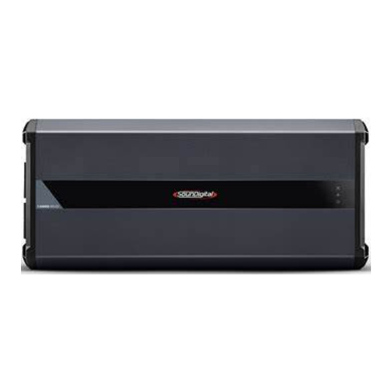
Summary of Contents for Soundigital 12000.1 EVO 4.0
- Page 1 OWNER´S MANUAL 12000.1...
-
Page 2: Table Of Contents
Introduction..............................3 Package contents ............................3 Safety instructions ............................4 Assembling and disassembling the plastic cover ..............5 Panels description Audio inputs and controls .................... 5 Power inputs and audio outputs ................7 Installation sequence..........................8 Electrical dimensioning ........................... 9 Audio inputs RCA inputs.......................... -
Page 3: Introduction
IMPORTANT INFORMATIONS On this manual you will learn about the product, its features and characteristics, in order to obtain the best result and to be able to enjoy your music with SounDigital quality and power. To better understand and take advantage of all the functions of the product and use it safely, read this manual carefully and if you have any questions, consult our support by email info@soundigitalusa.com. -
Page 4: Safety Instructions
Make sure the cables are properly secured throughout the installation; Wear gloves, safety glasses and all necessary PPE during the installation of SounDigital amplifiers. THIS "WARNING" SIGN ALERTS THE USER OF IMPORTANT INFO. NOT FOLLOWING THESE INSTRUCTIONS MAY CAUSE INJURIES TO THE USER OR DAMAGE TO THE EQUIPMENT. -
Page 5: Assembling And Disassembling The Plastic Cover
ASSEMBLING AND DISASSEMBLING THE PLASTIC COVER The plastic covers have the function of finishing and hiding the amplifier fixing screws. To disassembling and assembling them, follow the instructions below. DISASSEMBLING OF THE PLASTIC COVER 1. Carefully pull out the top of the plastic cover to release the upside latches, as shown in picture 1. 2. -
Page 6: Panels Description
PANELS DESCRIPTION Blue "POWER ON" LED indicator Yellow "CLIP" LED indicator "PROTECTION" LED indicator Variable Bass Boost Control 50Hz (0dB ~ +12dB) Variable Gain control Variable Low Pass filter control (50Hz ~ 6kHz) Variable High Pass filter control (5Hz ~ 80Hz) Audio input RCA connectors Audio output... -
Page 7: Power Inputs And Audio Outputs
PANELS DESCRIPTION 14 15 Negative power supply connector (GND) Remote power supply connector (REM) Positive power supply connector (+12VDC) -
Page 8: Installation Sequence
INSTALLATION SEQUENCE BEFORE PROCEEDING WITH THE INSTALLATION, UNPLUG THE NEGATIVE TERMINAL FROM ALL OF THE BATTERIES, TO AVOID FIRE, DAMAGE TO THE AMPLIFIER AND THE USER HIMSELF. Warning! Ø Mount the amplifier in such a way you have access to the connectors; Ø... -
Page 9: Electrical Dimensioning
ELECTRICAL DIMENSIONING AND AUDIO INPUTS ELECTRICAL DIMENSIONING For proper operation of your SounDigital amplifier, you need the proper dimensioning of the electrical system and the cables used. The table below shows the minimum section of GND cables, +12VDC cables and speaker output cables according to the power generated by the amplifier. -
Page 10: Sd Rlc And Gain Setting
SD RLC / GAIN SETTING EXTERNAL LEVEL CONTROL - SD RLC (*Not included) The SD RLC is an easy-to-install external level control accessory that allows you to tune the level of SOUNDIGITAL amplifiers that have remote level control. POWER CLIP... -
Page 11: Bass Boost Set Up
BASS BOOST AND CROSSOVER SET UP Using Bass Boost The Amplifier Bass Boost setting enables the user to boost the sound intensity at low frequencies of the sound system, where boost intensity can be adjusted. This is a semi-parametric equalizer type circuit with ''Q'' value for the fixed filter, with an intensity boost adjustment from 0 to +12dB (16 times), and a central frequency adjustment of the filter in 50Hz, making it versatile for several types of sound systems. -
Page 12: Wiring Diagram
WIRING DIAGRAM Unplug the negative (-) terminal of the battery before proceeding with any eletrical installation in the vehicle to avoid fire starts, wounds or damage to the amplifier. POWER CONNECTIONS In case of connections with more than one battery, see the installation diagram on page 3 FUSE... -
Page 13: Battery Connection Diagram
BATTERY CONNECTION DIAGRAM When necessary the association of one or more battery banks to supply the necessary current to the amplifier, it is recommended to use batteries of the same brand, model, and if possible the same manufacturing lot so that the system has the maximum performance. -
Page 14: Parameters
The values presented are based on measurements performed in Updates of information made in this document will always be SounDigital's laboratories. All the equipment used in the assays, tests, published and made available for consumer consultation, free of measurements and gauging of the technical parameters of SounDigital charge, on the brand's websites.


Need help?
Do you have a question about the 12000.1 EVO 4.0 and is the answer not in the manual?
Questions and answers