Table of Contents
Advertisement
Quick Links
Advertisement
Table of Contents

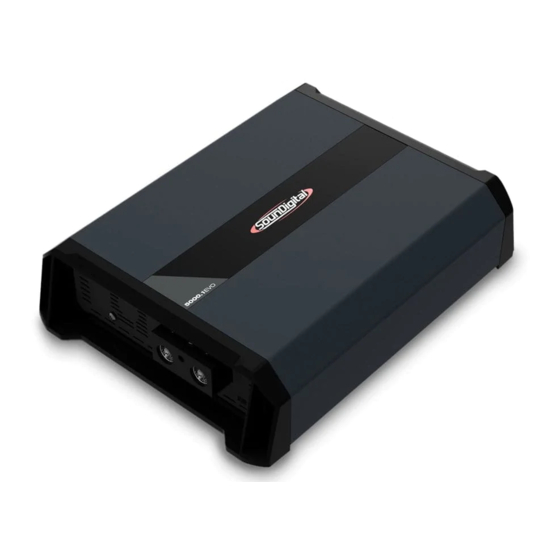
Summary of Contents for Soundigital 5000.1 EVO 4.0
- Page 1 OWNERS MANUAL 5000.1...
-
Page 2: Table Of Contents
TABLE OF CONTENTS Introduction..........................Package contents......................Safety instructions......................Montagem e desmontagemda capa plástica..........Panels description Audio inputs and controls..............Power inputs and audio outputs............Electrical Dimensioning....................Audio input and output....................Installation sequence....................... Wiring diagram........................Procedure for setting the gain.................. Crossovers set up......................Using the Bass Boost.................... -
Page 3: Introduction
Class D amplifier superior to the Class AB ones in efficiency and performance. Efficiency - The Soundigital Class D amplifiers have a total efficiency (power source + output) higher than 70%, assuring a battery consumption and a heating lower than the expected. -
Page 4: Safety Instructions
Make sure the cables are properly secured throughout the installation; Wear gloves, safety glasses and and all necessary PPE during the installation of SounDigital amplifiers. THIS "WARNING" SIGN ALERTS THE USER OF IMPORTANT INFO. NOT FOLLOWING THIS INSTRUCTIONS MAY CAUSE INJURIES TO THE USER OR DAMAGE TO THE EQUIPMENT. -
Page 5: Montagem E Desmontagemda Capa Plástica
ASSEMBLING AND DISASSEMBLING THE PLASTIC COVER The plastic covers have the function of finishing and hiding the amplifier fixing screws. To disassembling and assembling them, follow the instructions below. DISASSEMBLING OF THE PLASTIC COVER 1. Carefully pull out the top of plastic cover to release the upside latches, as shown in the picture 1. 2. -
Page 6: Panels Description
PANELS DESCRIPTION 9 10 INPUT Audio input - RCA connector OUTPUT Variable High Pass filter control (5Hz ~ 80Hz) X-OVER Variable Low Pass filter control (50Hz ~ 20kHz) Variable Gain Control GAIN Variable bass boost control (0dB - +12dB/50Hz); Bass Boost Level Remote Level Control Remote level control connector Negative speaker connector... -
Page 7: Power Inputs And Audio Outputs
PANELS DESCRIPTION Positive power supply connector (+12v) ALIMENTAÇÃO Remote power supply connector (REM) Negative power supply connector (GND) -
Page 8: Electrical Dimensioning
ELECTRICAL DIMENSIONING AND AUDIO INPUTS ELECTRICAL DIMENSIONING For proper operation of your SounDigital amplifier, you need the proper dimensioning of the electrical system and the cables used. The table below shows the minimum section of GND cables, +12VDC cables and speaker output cables according to the power generated by the amplifier. -
Page 9: Installation Sequence
INSTALLATION SEQUENCE Warning! Mount the amplifier in such a way you have access to the connectors; Ø Install the power cables in the vehicle properly, starting from the battery to the fuse Ø holder or circuit breaker, use the cable with the appropriate size. Make all connections, install fuse holders or circuit breakers, but without placing the fuses or with the circuit breakers in the "Off"... -
Page 10: Wiring Diagram
WIRING DIAGRAM AUDIO INPUT AND OUTPUT CONNECTIONS POWER SUPPLY CONNECTIONS REMOTE +12V +12V FUSE FUSE... -
Page 11: Procedure For Setting The Gain
CROSSOVER SET UP How to Adjust the Crossovers Set in the variable control "HIGH" between 5 Hz and 80 Hz ("A") where you want to perform the high pass cut filter; -3dB -15dB ƒ ƒ High High Pass Pass Set in the variable control "LOW" between 50 Hz and 20 kHz ("B") where you want to perform the low pass cut filter;... -
Page 12: Using The Bass Boost
USING THE BASS BOOST Using Bass Boost The Amplifier Bass Boost setting enables the user to boost the sound intensity at low frequencies of the sound system, where boost intensity can be adjusted. This is a semi-parametric equalizer type circuit with ''Q'' value for the fixed filter, with an intensity boost adjustment from 0 to + 12dB (16 times), and a central frequency adjustment of the filter in 50Hz, making it versatile for several types of sound systems. - Page 13 GAIN SETING Necessary equipament: Use a 60 Hz sine wave Ø Digital AC voltmeter; Ø Ø Increase the gain control until the Media with sine wave test tone 60Hz "CLIP" LED starts blinking; Ø recorded at 0db; Ø Return the gain to the limit where Screwdriver 1/8"...
-
Page 14: Technical Specs
TECHNICAL SPECS PARAMETERS 5000.1 5000.1 Ω Ω Power RMS @ 4Ω* 2178W 3300W Power RMS @ 2Ω* 3300W 5000W Power RMS @ 1Ω* 5000W Frequency Response (-3dB) 5Hz ~ 20kHz 5Hz ~ 20kHz Low Pass filter (LP -12dB/8) 50Hz - 20kHz 50Hz ~20kHz High Pass filter (HP -12dB/8) 5Hz ~80Hz...


Need help?
Do you have a question about the 5000.1 EVO 4.0 and is the answer not in the manual?
Questions and answers