Advertisement
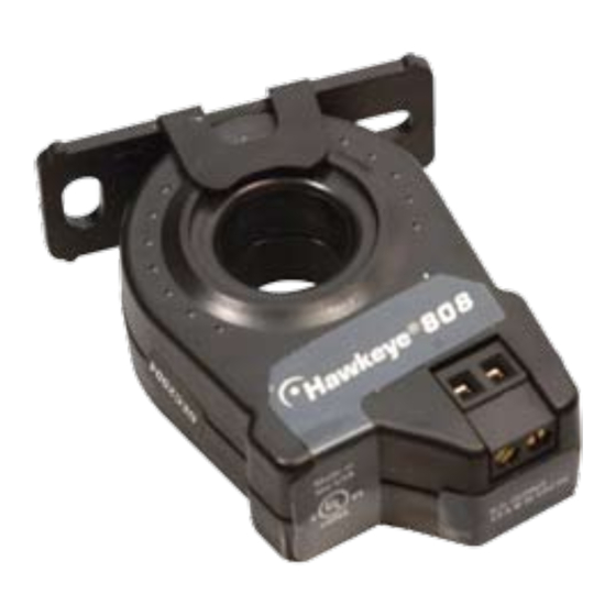
H808
Wiring Example
CONTACTOR
Motor
Z201763-0D
PAGE 1
CURRENT MONITORING
Insulated Conductor Only
DDC CONTROLLER
DI
Fan or Pump
©2007 Veris Industries USA 800.354.8556 or 503.598.4564 / support@veris.com
INSTALLATION GUIDE
Mini Adjustable Solid-Core
Current Switch
Installer's Specifications
Amperage Range
Sensor Supply Voltage
Isolation
Temperature Range
Humidity Range
Status Output Ratings
Off-state Leakage
*When operating at 50 Hz., low threshold may be .9A.
Specification Note: For CE compliance, conductor shall be insulated according to IEC 61010-1:2001, Installation
Category III or equivalent. The unit design provides for basic insulation only.
quick install
1. Plan the installation:
Locate a mounting surface for the removable mounting bracket that will allow
the monitored conductor to pass through the iris, or "window" when it is installed
and keep the product at least 1/2" (13mm) from any uninsulated conductors (CE).
Determine cable routing for the controller connection, allowing wiring to reach the
mounting location.
2. Install mounting bracket
Drill holes to mount the bracket to the chosen surface using the included screws.
3. Wire the output connections between the sensor and the controller (solid-state
contact) or external power supply.
4. Route the wire to be monitored through the product iris and slip the assembly into
the mounting bracket.
5. Calibrate the sensor (see page 2) with the load running normally.
6. Close up and power up!
Dimensions
.4" x .2"
Slot (x2)
Removable/Adjustable Mounting Bracket
808
.75-50A Continuous
Induced from monitored conductor
600VAC rms. (UL), 300VAC (CE)
10-90% RH non-condensing
N.O. 1.0A@30VAC/DC not polarity sensitive
0 (open switch represents 1+ MEG ohms of resistance)
1.7
(43 mm)
1.2"
(30 mm)
2.3"
(58 mm)
ø 0.7"
(18 mm)
1.0"
(25 mm)
2.8"
(71 mm)
-15º to 60º C
03071
Advertisement
Table of Contents

Related Manuals for Veris Industries Hawkeye 808


Summary of Contents for Veris Industries Hawkeye 808
- Page 1 Insulated Conductor Only (30 mm) CONTACTOR 2.3" DDC CONTROLLER (58 mm) Removable/Adjustable Mounting Bracket ø 0.7" (18 mm) 1.0" (25 mm) 2.8" (71 mm) Fan or Pump Motor Z201763-0D PAGE 1 ©2007 Veris Industries USA 800.354.8556 or 503.598.4564 / support@veris.com 03071...
- Page 2 Twenty turns CCW will reset the sensor to be most sensitive. reading must be divided Repeat calibration above. by 4. Both LEDs are lit Unit is out of calibration. Turn screw 20 turns CCW and recalibrate. Z201763-0D PAGE 2 ©2007 Veris Industries USA 800.354.8556 or 503.598.4564 / support@veris.com 03071...
Need help?
Do you have a question about the Hawkeye 808 and is the answer not in the manual?
Questions and answers