Advertisement
Quick Links
Advertisement

Related Manuals for Digitus DA-90453


Summary of Contents for Digitus DA-90453
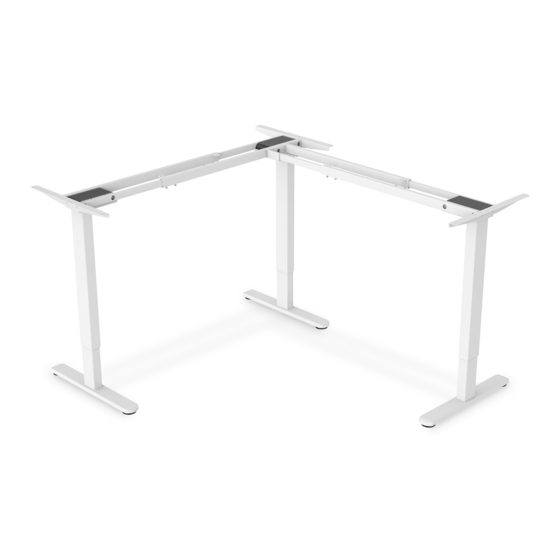
- Page 1 Electrically Height-Adjustable Table Frame Manual DA-90453...
- Page 2 1. Introduction With this electrically height-adjustable table frame from DIGITUS® you can easily convert your desk into an ergonomic sit / stand workstation. Save the cost and hassle of finding a height-adjustable desktop and just use our electrically adjustable upgrade kit. This model can be used for tabletops with a length of 120-180 cm and 140-200 cm.
- Page 3 4. Technical Data Maxiumum load up to 120 kg capacity Cross strut (112 - 165 cm) x longitudinal strut Flexibly adjustable frame (130 - 180 cm) 120 - 180 cm x 140 - 200 cm and a depth of Suitable for tabletops 55 - 75 cm The longitudinal strut (3rd leg) can be flexible installed on the left or right Convenient, electrical...
- Page 4 5. Accessory List Attention: The drawings below are for guidance only and they may differ slightly from the product and fittings received. Please contact our customer service department if you have any queries. Image Specification Number M5 x 16 mm 24+2 M6 x 11 mm 42+2...
- Page 5 Tablestop Connector Foot Pad 6. Component list Part Part Feet Lifting column Side bracket Connection arm Connection rod Connection rod Connection rod Connection rod...
- Page 6 Connection rod Handset Control Box Power plug Adapter cable 1M Adapter cable 1.3M...
- Page 7 7. Assembly instruction Step 1: Install the feet Connect the feet (l) and the lifting column (2) with screws (B), and tighten them with the allen key (E). Step 2: Install the connection rod. Using screws (B) to connect the lifting column with connection rods (5) and (6) and tighten them with the allen key (E).
- Page 8 Step 3: Install the connection rod. Using screws (B) to connect the lifting column with connection rods (6) and (7) and tighten them with the allen key (E). Insert two connection rods (6) into connection rods (5) and (7) respectively.
- Page 9 Step 4: Install the connection arm. Connect the connection arm (4) to the connection rod (7) with screws (C) and tighten them with the allen key (E). Step 5: Install the connection rod Connect connection rods (8) and (9) to the connection arm (4) with screws (B), and tighten them with the allen key (E).
- Page 10 Step 6: Install the connection rod. Using screws (B) to connect the lifting column with connection rods (5) and (6) and tighten them with the allen key (E). Insert the connection rod (6) into the connection rod (8). Insert the connection rod (9) into the connection rod (5).
- Page 11 Step 7: Fix the connection rod. Adjust Tighten Adjust the length according to the table size, then fix the frame with screws (B). Step 8: Install the side bracket. Connect side brackets(3) to lifting columns(2) with screws(B), and tighten them with the allen key (E).
- Page 12 Step 9: Install the rubber pads. Step 10: I nstall the tabletop.
- Page 13 Step 11: Install the tabletop, control box.
- Page 14 Step 12: Connect cables and power plug. Cable Management Port for adapter cable Port for cable connected to Port for the lifting column handset...
- Page 15 8. Common fault treatment Adjust the desk upwards Adjust the desk downwards Height Preset 1 Height Preset 2 Height Preset 3 Height Preset 4 To set Height Preset, press the M button until LED Display flashes then Preset 1, 2, 3 or 4 to program preset Error Code Troubleshoot (Shown on LED Display) Over-heating Alarms when continuously in motion for 2...
- Page 16 alarms when desk is moving down, turn off the power, remove loads off the desk and re-try. Rebound Alarms when vibrated, collided or inclined during protection height adjustment. Check if there is anything in the way of desk motion. Then proceed to the reset the motor.
- Page 17 “M” again and the display shows “Un”. Press or to switch to “br”. Press “M” to select. Press or to switch between Low (L), Normal (n) or High (H) brightness. Press “M” to save your choice. Collision Force Detection (CF) Press and hold the “M”...
- Page 18 Children are forbidden to play on the product because of unforeseen actions when playing, so any dangerous consequences caused by this improper action will not be manufacturers. Children are forbidden to play with the appliance at all Be familiar with all functions and program settings of the product before first use Check carefully to ensure correct and complete assembly before using Cleaning and user maintenance shall not be made by children without...
- Page 19 position. The table shall only be used indoors and in dry premises (office environment or similar). 18. The table must not be overloaded – maximum load is 120 kg 19. The motors may be run continuously for maximum 2 minutes. Afterward, the motors must stand by for approx.
- Page 20 Disclaimer Hereby Assmann Electronic GmbH, declares that the Declaration of Conformity is part of the shipping content. If the Declaration of Conformity is missing, you can request it by post under the below mentioned manufacturer address. www.assmann.com Assmann Electronic GmbH Auf dem Schüffel 3 58513 Lüdenscheid Germany...
Need help?
Do you have a question about the DA-90453 and is the answer not in the manual?
Questions and answers