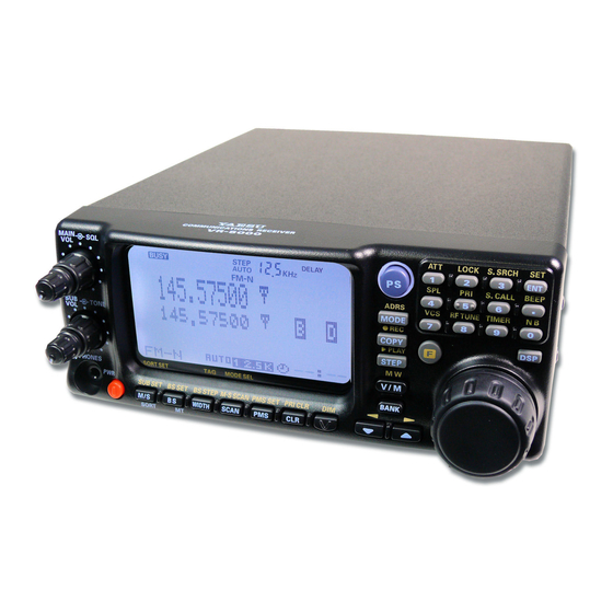
Yaesu VR-5000 Operating Manual
All mode communications receivers
Hide thumbs
Also See for VR-5000:
- Operating manual (28 pages) ,
- Brochure & specs (4 pages) ,
- Manual (3 pages)
Table of Contents
Advertisement
Quick Links
O
M
PERATING
ANUAL
VERTEX STANDARD CO., LTD.
4-8-8 Nakameguro, Meguro-Ku, Tokyo 153-8644, Japan
VERTEX STANDARD
US Headquarters
10900 Walker Street, Cypress, CA 90630, U.S.A.
YAESU EUROPE B.V.
P.O. Box 75525, 1118 ZN Schiphol, The Netherlands
YAESU UK LTD.
Unit 12, Sun Valley Business Park, Winnall Close
Winchester, Hampshire, SO23 0LB, U.K.
VERTEX STANDARD HK LTD.
Unit 5, 20/F., Seaview Centre, 139-141 Hoi Bun Road,
Kwun Tong, Kowloon, Hong Kong
Advertisement
Table of Contents

Related Manuals for Yaesu VR-5000


Summary of Contents for Yaesu VR-5000
- Page 1 4-8-8 Nakameguro, Meguro-Ku, Tokyo 153-8644, Japan VERTEX STANDARD US Headquarters 10900 Walker Street, Cypress, CA 90630, U.S.A. YAESU EUROPE B.V. P.O. Box 75525, 1118 ZN Schiphol, The Netherlands YAESU UK LTD. Unit 12, Sun Valley Business Park, Winnall Close Winchester, Hampshire, SO23 0LB, U.K.
-
Page 2: Table Of Contents
Introduction ... 1 Supplied Accessories ... 1 Available Option ... 1 Front Panel Controls & Switches ... 2 Rear Panel Connections ... 6 Installation ... 8 Power connections ... 8 Antenna considerations ... 9 Basic Operation ... 14 Introduction ... 14 Turning the Power On/Off ... -
Page 3: Introduction
The procedures described below will ensure that you get the most out of your new VR-5000 receiver. After carefully removing the VR-5000 from its packing carton, inspect it for any signs of physical damage. Rotate the knobs and push the switches, checking each for normal free- dom of action. -
Page 4: Front Panel Controls & Switches
‡G ‡G ‡D ‡D ‡G ‡G ‡D ‡D ‡D BS STEP M-S SCAN PMS SET PRI CLR SCAN ‡E ‡E ‡E ‡E ‡E VR-5000 O ‡F ‡F ‡F ‡I ‡I ‡I ‡K ‡K ‡K ‡F ‡F ‡I ‡I ‡K ‡K LOCK S.SRCH... -
Page 5: Function Keys
Front Panel Controls & Switches PWR Knob This is the main on/off switch for the VR-5000. Press and hold this switch for one second to toggle the receiver’s power on and off. LCD (Liquid Crystal Display) The upper half of the display consists of a dot-matrix display for frequency readout, plus various icons representing enabled receiver features. - Page 6 Press this key momentarily to copy the SUB VFO data into the MAIN VFO. Press this key after [ ] key is pressed to start the voice recorder. key is pressed to activate the optional FVS-1A Voice Synthe- VR-5000 O...
- Page 7 Press this key momentarily to activate the optional DSP-1 Digital Signal Processing Unit. DIAL Knob This is the main tuning dial for the VR-5000. It is used for most tuning, memory selection, and function setting tasks on the VR-5000. VR-5000 O...
-
Page 8: Rear Panel Connections
‡E ‡E DC 13.5V Jack This is the DC power supply connection for the VR-5000. Connect the Supplied PA- 28 AC adapter to this jack. MUTE Jack If using the VR-5000 with a transceiver, shorting this jack during transmit will mute receiver output and attenuate the RF signal input. - Page 9 This output jack provides low-level 10.7 MHz IF output. Jack This 9-pin serial DB-9 jack allows external computer control of the VR-5000. Con- nect a serial cable here and to the RS-232C “COM” port on your personal computer. VR-5000 O...
-
Page 10: Installation
To install the PA-28, first connect the small, round DC output connector on the cable of the PA-28 to the DC 13.5V jack on the rear panel of the VR-5000. Then plug the PA-28 into the AC wall outlet. -
Page 11: Antenna Considerations
We recommend that, when using an external DC power supply, you turn the power supply on, then turn on the VR-5000; when shutting down, turn the VR-5000 off first, then turn off the power supply. If the input voltage becomes too low (due to power supply failure or a problem in the DC cable), the VR-5000’s display will indicate “ERROR LOW VOLTAGE”... - Page 12 Optimum performance on frequencies between 2 and 30 MHz will generally be obtained through use of a resonant antenna with an impedance near 50 Ohms at the frequency of interest. Broadband or multiband “Dipole” antennas, such as the Yaesu model YA-30, are available from your dealer.
- Page 13 ANT A/B slide switch, located between the two antenna jacks on the rear panel of the VR-5000. An antenna may be connected to each jack; there is no need to remove an antenna when the alternate jack is being used.
- Page 14 Typically, such a transmitter will have an internal relay, the contacts of which will close to ground during transmission; connection of a cable connected to this type of switching system will cause the audio output from the VR-5000 to be cut off (when the center con- ductor is shorted to ground).
- Page 15 A portion of the 10.7 MHz Intermediate Frequency (IF) stage signal is available via this jack. This may be used for observing signal characteristics, or a separate receiver may be connected here to monitor FM broadcast sub-carrier signals, etc. VR-5000 O...
-
Page 16: Basic Operation
VFO may simply be thought of as a tuning dial for the receiver. Details regarding setup and operation of the VR-5000 are found in the pages to follow. Press and hold the orange PWR switch for one second to turn the radio on and off. The one-second delay minimizes the chance that the radio will accidentally be turned on or off by bumping the PWR switch. -
Page 17: Mode Selection
Pressing the [ ( ) / ( )] keys allows tuning in the pre-programmed steps established for the current receiving band. Pressing the [ ( )] key causes the VR-5000 to be tuned toward a higher frequency, while pressing the [ ( )] key will lower the receiving frequency. -
Page 18: Channel Step Selection
Basic Operation Operation of the VR-5000 initially is set up in the “AUTO” mode (mentioned in the previ- ous section), whereby the reception mode (such as AM or FM) is automatically set accord- ing to the frequency in use; at the same time, the channel steps typically used in that fre- quency segment are also programmed automatically. -
Page 19: Setting The Clock
10. Press the [ F ] key momentarily, then press the press the [ 9 TIMER ] key. 11. Press the [ CLR PRI CLR ] key then press the [ ENT SET ] key. 12. Setup of the clock is now complete. VR-5000 O Basic Operation... -
Page 20: Receiving Short-Wave Broadcast Stations
3. Rotate the DIAL knob to select the Broadcast Station’s frequency from among the pre- programmed choices. At different times of the day, different frequencies will be opti- mum for each station. 4. To exit from the special Short-wave Broadcast Station Memory Bank, press the [ CLR PRI CLR ] key. VR-5000 O... - Page 21 INDIA All India Radio (AIR) CHINA-R China Radio International (CRI) R-KOREA Radio Korea R-JAPAN Radio Japan R-AUSTRA Radio Australia VR-5000 O Basic Operation frequency of the Broadcast Station on the list. Frequency (MHz) 6.030/6.160/9.760/11.930 5.995/7.235/9.735/11.705 9.780/11.960/15.555/21.655 7.270/9.520/11.920/15.585 6.195/9.410/12.095/15.310 6.045/9.790/11.670/15.525 5.985/9.925/11.780/13.740 5.955/6.020/9.895/11.655...
-
Page 22: Memory Operation
Memory Operation The VR-5000 provides a wide variety of memory system resources. These include: Ì 2000 main memory channels, which may be separated into as many as 100 memory groups. Ì 50 sets of band-edge memories (also known as “Programmable Memory Scan” channels). - Page 23 You can also configure the VR-5000 for recall of all memory channels (ignoring the memory groups). To do this: (1) Press the [ F ] key momentarily, then press the [ ENT ( SET )] key. (2) Rotate the DIAL knob to set the cursor to the “MR” menu, then press the [ ENT ] key.
-
Page 24: Enhanced Memory Channel Operation
Once you have recalled a particular memory channel, you may easily tune off that channel, as through you were in the “VFO” mode. 1. With the VR-5000 in the memory mode, select the desired memory channel. 2. Press the [ BS ( BS SET ) MT ] key momentarily. - Page 25 Ì Press the [ CLR ( PRI CLR )] key, after the [F] key is pressed, to cancel the all charac- ters. VR-5000 O Memory Operation « “ ( ” « “ ) ” « “*” « “+” « “ : ” « “ ! ”…...
-
Page 26: Naming Memory Groups
5. Rotate the DIAL knob to set the cursor to the “WRITE” menu option, then press the [ ENT ( SET )] key to protect the channel’s data. If you set the “PROTECT” menu to “FREE” in step 4, the memory protection feature will be disabled. VR-5000 O... -
Page 27: Masking Memories
6. Rotate the DIAL knob to set the cursor to the “END” menu, then press the [ ENT ( SET )] key. 7. Confirm that the cursor is on the “WRITE” menu option, then press the [ ENT ( SET )] key to unmask the channel. VR-5000 O Memory Operation... -
Page 28: Alpha-Numeric Memory Recall
“PORTLAND,” and “POLAND” in addition to “POLICE.” But if you set “POR,” only “PORTER” and PORTLAND” would be recalled. The VR-5000 can be set up to monitor the activity on as many as 50 memory channels simultaneously. For example, repeater system owners may wish to observe channel load- ing on the various repeaters in the system, and the VR-5000 can assist in this effort. - Page 29 5. Confirm that the cursor is on the “WRITE” menu, then press the [ ENT ( SET )] key to delete the memory channel from the PMR Board and return to the Memory mode. VR-5000 O Memory Operation ” menu, then press the [ ENT ( SET )]...
-
Page 30: Memory Channel Sort
Memory Operation The VR-5000 can also sort the memory channels according to “Alpha-Numeric Name Tag,” “Frequency,” “Receive mode,” or “Channel Number.” When this is done, the memory channel numbers will be re-arranged to reflect the new lineup of the memorized channels. -
Page 31: Ps (Preset) Memory Channel
Note: When you initiate Channel Number Sorting, the VR-5000 can not recall Masked memory channels. PS ( P S ) M Five convenient PS memories are provided in the VR-5000, allowing quick recall of top- priority operating frequencies. Use this memory feature for your most-often-used frequen- cies. -
Page 32: Scanning
Scanning The VR-5000 allows you to scan just memory channels, the entire operating band, or a portion of that band. It will halt on signals encountered, so you can listen to the station(s) on that frequency, if you like. Scanning operation is basically the same in each of the above modes. There are customized settings for each scanning mode, however, that you need to set up according to your oper- ating preferences. - Page 33 5. Rotate the DIAL knob to select “END,” then press the [ ENT ( SET )] key . 6. The display should now indicate “WRITE;” press the [ ENT ( SET )] key again to save the new setting and exit to normal operation . VR-5000 O Scanning...
-
Page 34: Memory Scanning
DIAL knob one click in the counter-clock direction (or press the [ ( )] key momentarily) while the VR-5000 is scanning. To revert to scanning toward a higher memory channel once more, rotate the DIAL knob one click clockwise (or press the [ ( )] key momentarily). - Page 35 DIAL knob one click in the counter-clock direction or press the [ ( )] key momentarily (while the VR-5000 is scanning). To revert to scanning to- ward a higher frequency once more, rotate the DIAL knob one click clockwise (or press the [ ( )] key momentarily).
-
Page 36: Memory Scan (Pms)
This allows you to monitor only a portion of the wide frequency range of the VR-5000, instead of sweeping the entire spectrum from 100 kHz to 2.6 GHz. Programmable Memory Scan utilizes a pair of special memories to establish the upper and lower scanning limits. - Page 37 DIAL knob one click in the counter-clock direction or press the [ ( )] key momentarily while the VR-5000 is scanning. To revert to scanning toward a higher frequency once more, rotate the DIAL knob one click clockwise or press the [ ( )] key momentarily.
-
Page 38: M-S Scan
DIAL knob one click in the counter-clock direction or press the [ ( )] key momentarily while the VR-5000 is scanning. To revert to scanning toward a higher frequency once more, rotate the DIAL knob one click clockwise or press the [ ( )] key momentarily. -
Page 39: Band Scope Operation
A convenient “Channel marker” can be used to zero in on one of the stations displayed; when you turn off the Band Scope, the VR-5000 will be set to the frequency set by the Channel Marker. -
Page 40: Smart Search Operation
To recall the Smart Search Memories: 1. Recall the Memory mode. 2. Using the [ ( ) / ( )] key or keypad, select the Memory Bank for the Smart Search. 3. Rotate the DIAL knob to select Smart Search Memory. VR-5000 O... -
Page 41: Priority Operation
Priority Channel, the VR-5000 will automatically switch to that channel. If no activity is encountered on the Priority Channel, you can operate on other memory chan- nels (and even scan, if desired), and the VR-5000 will continue to poll the Priority Chan- nel, looking for activity. -
Page 42: World Clock
World Clock The VR-5000 provides a World Clock with time references to 66 different areas of the world, for quick time zone recognition. 1. Press the [ F ] key momentarily, then press the [ 4 SPL ] key. 2. Confirm that the cursor is on the “WORLD TIME” menu, then press the [ ENT SET ] key. - Page 43 3. Program the area name (max 8 characters) using the DIAL knob and keypad, as de- scried previously then press the [ ENT ( SET )] key. In this case “Cerritos.” 4. Confirm that the cursor is on the “WRITE” menu, then press the [ ENT ( SET )] key. VR-5000 O...
-
Page 44: Timer Operation
Timer Operation The Program timer can be utilized to set the VR-5000 to user-programmed frequencies automatically at preset times. This is particularly convenient if you want to be sure not to miss programs of particular interest. Programming: 1. Set the Main VFO to the desired receiving frequency (the frequency to which you want the VR-5000 to switch automatically). -
Page 45: Sleep Timer
6. Confirm that the cursor is on the “WRITE” menu, then press the [ ENT ( SET )] key. When activate the Alarm Timer, appear the “ play in the LCD. VR-5000 O Timer Operation ” icon above the MAIN frequency dis-... -
Page 46: Dsp Operation
DSP Operation Digital Signal Processing is a highly-effective fitering technology which can dramatically improve reception. The optional DSP Unit (DSP-1) brings to the VR-5000 the following four features: Ì DSP NOTCH Filter Ì DSP Bandpass Filter Ì DSP CW Peaking Filter Ì... -
Page 47: Dsp Cw Peaking Filter
6. Confirm that the cursor is on the “UPDATE” menu, then press the [ ENT ( SET )] key to exit the setup procedure. 7. Press the [ DSP ] key to activate the DSP system. To disable the DSP CW Peaking Filter, set the “CW-BW” menu option to “OFF” in step 4. VR-5000 O DSP Operation... -
Page 48: Dsp Noise Reduction
Note: If you set the “CW-PITCH” menu item to “OFF” in step 2, it will automatically disable the CW Bandpass Filter. This is a “short-cut” to speed your progress through the Menu system. DSP N CW-PITCH VR-5000 O... -
Page 49: Miscellaneous Features
1. To disable the keypad beeper, press the [ F ] key momentarily, then press the [ • ( BEEP )] key. 2. If you wish to re-enable the keypad beeper, press the [ F ] key momentarily, then press the [ • ( BEEP )] key. VR-5000 O Miscellaneous Features ATT ( RF A NB ( N... -
Page 50: Locking Front Panel Controls
Miscellaneous Features In order to prevent accidental frequency change, the VR-5000’s front panel Controls may be locked out. 1. To lock out the Front Panel Controls, press the [ F ] key momentarily, then press the [ 2 ( LOCK )] key. The “KEY” icon will appear on the display. -
Page 51: Display Contrast
[ ENT ( SET )] key. 6. Confirm that the cursor is on the “WRITE” menu option, then press the [ ENT ( SET )] key to save the new setting and exit to normal operation. VR-5000 O Miscellaneous Features “H... -
Page 52: Voice Synthesizer Operation
• If you manually choose record in channel “DVR ch2,” the last 8 seconds of the contents of channel “DVR ch1” will disappear. Monitor 1. Press the [ F ] key momentarily, then press the [ MODE ( ADRS )] key. VR-5000 O... -
Page 53: Field Strength Meter
• If you select the “DVR ch2” channel for playback, it will play back audio for 8 seconds (irrespective of the actual recording time). The VR-5000 can provide display of the relative receiving signal strength on the LCD, compared to some user-defined “baseline” field strength. -
Page 54: Audio Wave Meter
Miscellaneous Features The VR-5000 can be set up to display the relative received audio wave-form on the LCD. 1. Press the [ F ] key momentarily, then press the [ 4 ( SPL )] key. 2. Rotate the DIAL knob to set the cursor to the “AUDIO WAVE” menu option, then press the [ ENT ( SET )] key. -
Page 55: Cloning
The VR-5000 includes a convenient “Clone” feature, which allows the memory and con- figuration data from one receiver to be transferred to another VR-5000. Here is the proce- dure for Cloning one radio’s data to another: 1. Set both radio’s baud rate to the same rate, such as “”57,600 bps,” per the following steps: (1) Press the [ F ] key momentarily, then press the [ ENT ( SET )] key. -
Page 56: Operation
The VR-5000 has a built-in level converter, allowing direct connection from the rear- panel jack to the serial port of your computer without the need of any external boxes. - Page 57 5-Byte Command Structure Parameter 1 (LCD) Parameter 2 Parameter 3 Parameter 4 Command Data There are three instruction opcodes for the VR-5000, listed in the table below. Most of these duplicate menu programming settings or options, or else emulate front panel button functions.
-
Page 58: Reset
2. Press and hold the [ CLR ( PRI CLR )] key while turing the Radio ON. 3. Press the [ ENT ( SET )] key to reset the all setting to their factory defaults (press the [ CLR ( PRI CLR )] key to cancel the Reset procedure). VR-5000 O... -
Page 59: Installation Of The Optional Accessories
2. Locate the empty 10-pin jack, and connect the FVS-1A here (see Figure 2). 3. Set JApanese/ENglish switch on the FVS-1A to the EN. 4. Replace the bottom cover and its four screw. ¬ ¬ Figure 1 VR-5000 O ( FVS-1A ) ¬ DSP-1 Mounting Position ¬... -
Page 60: Auto" Mode Preset
270.00000 ~ 271.00000 271.00000 ~ 275.00000 FM-N 12.5 275.00000 ~ 336.00000 336.00000 ~ 420.00000 FM-N 12.5 420.00000 ~ 450.00000 FM-N 450.00000 ~ 470.00000 FM-N 12.5 470.00000 ~ 770.00000 WFM 770.00000 ~ 1300.00000 FM-N 1300.00000 ~ 2599.99998 FM-N 12.5 VR-5000 O STEP (kHz) -
Page 61: Specifications
180 x 70 x 203 mm (W x H x D) w/o knob Case Size: Approx. 1.9 kg Weight: Specifications are subject to change without notice. VR-5000 O LSB/USB/CW : 20 Hz/100 Hz/500 Hz/1 kHz/5 kHz AM-N/AM/WAM : 1/5/9/10/20/25/50/100/500 kHz FM-N : 5/6.25/10/12.5/20/25/50/100/500 kHz... - Page 62 Note VR-5000 O...
- Page 63 “This scanner receiver is not a digital scanner and it is incapable of being converted or modified to a digital scanner receiver by the user.” This equipment has been tested and found to comply with the limits for a Class A Digital device, pursuant to Part 15 of the FCC Rules.
- Page 64 Copyright 2003 VERTEX STANDARD CO., LTD. All rights reserved. Printed in Japan 0303Y-EY No portion of this manual may be reproduced without the permission of VERTEX STANDARD CO., LTD.
Need help?
Do you have a question about the VR-5000 and is the answer not in the manual?
Questions and answers