Table of Contents
Advertisement
Quick Links
Advertisement
Table of Contents

Related Manuals for Yaesu FRG-100


Summary of Contents for Yaesu FRG-100
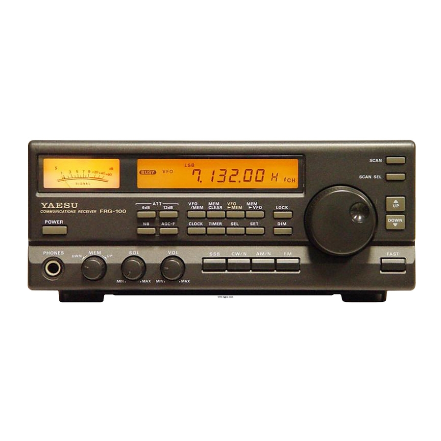
- Page 1 Operating Manual YAESU MUSEN CO., LTD.
-
Page 2: Table Of Contents
Noise Rejection Cover Screws Noise Blanker Setting ..CAT Control System RF Attenuation Beep Settings Data Returned From FRG-100 Changing Receiver Selectivity FRG-100 CAT Commands PLL Offset Status Update Data Organization .. - Page 3 The Yaesu CAT system provides a direct link to vides frequency read-out and important opera- the CPU in the FRG-100, allowing a personal com- tional status at a single glance. Selectable tuning puter with the Yaesu FIF CAT Interface Unit to add...
-
Page 4: Specifications
Specifications Frequency Range: 50 kHz 30 Mhz Circuit Type: dual- conversion superheterodyne Reception Modes: USB. LSB. AM, FM (optional) Intermediate Frequendes: lst IF 47.21 MHz < Frequency Stability: f 10 ppm, from -10 -+50 2nd IF 455 kHz < f 2 ppm, from 0 (w/TCXO option) Squelch Sensistivity:... -
Page 5: Accessories & Options
Accessories Options & Supplied Accessories Mini Phone Plug Sub-Mini Phone Plug DC Power Cord (T9019399) 1 ea. (P0090034) 1 ea. (P0090970) 1 ea. RCA Plug (P0090544) 1 ea. Fuse (Q0000021) 2 ea. Options CW Narrow Filter YF-110 CICN (5001250 Hz) -
Page 6: Front Panel Controls & Connectors
Front Panel Controls Connectors & POWER This button turns the receiver again will toggle between USB and LSB mode, on/off, however, the clock and memory backup pressing the CWIN and AMIN keys a second time functions stay on and are not affected. To avoid will select the narrow filter (if installed). -
Page 7: Liquid Crystal Display
MEM bVFO Shifts the contents of the selected The noise blanker helps to reduce inter- memory channel into VFO without erasing the ference experienced from man-made impulse-type stored memory data. noise. Normally, if noise is not present, this switch CLOCK Used to select and enter the correct should be kept in the un-depressed position. -
Page 8: Rear Panel Controls & Connectors
(GND). Check with information provided with your par- 2 CAT This 6-pin DIN plug allows external ticular transceiver for proper connection. computer control of the FRG-100 when used with 7 ANT LO-Z Connect the 50 coaxial feed line the optional FIF Interface and software. See the to your low-impedance antenna here using a type- CAT Control System chapter for details. -
Page 9: Receiver Installation
A wire connect the GND terminal on the receiver ante, bail on the bottom of the FRG-100 can be folded rear panel to a good earth ground, using a down for this purpose. A handy laminated world braided cable length possible. -
Page 10: Shortwave Signals & Propagation
Shortwave Signals and Propagation cow. However, the path from Tokyo to New York is largely a daylight path, and as discussed earlier, it Shortwave signals are transmitted by stations would be difficult, if not impossible, to hear Tokyo running high power output and use elaborate an- at the same time and frequency. -
Page 11: Antenna Considerations
FRG-100 can be used with an indoor overloading, but also reduces the strength of the or "active" antenna. In most cases, however, a desired signals. -
Page 12: Dipole Construction
Performance on a specific band can be achieved Important! using a simple resonant dipole antenna, consisting For proper reception, ensure that the LO-Z of two equal-length wires cut for the center of the HI-Z antenna selector switch on the rear panel desired band. -
Page 13: Typical Antenna Installations
HI-Z 1 0 1 Typical LF-MW Antenna Installation HI-Z Typical Antenna Installation... -
Page 14: Power-Up
Butt on Combination Settings & By pressing and holding certain buttons while turning on the FRG-100, you can change many default settings, and customize features to your own preference. Other important settings can be selected by pressing and holding the SET button with other key combinations, as described in the bottom table. -
Page 15: Operation
Frequency Tuning Getting Started Tutoria I The FRG-100 provides a combination of the Basic operation of the FRG-100 is simple, how- main tuning knob, up/down keys, and selectable ever, some of the more advanced features can be tuning speeds to allow fast and accurate frequency confusing at first if you are not familiar with their selection. -
Page 16: Programmable Tuning Steps
Programmable Tuning Steps holding the FAST key while powering on again. Now, the FAST key/function is enabled only as The FRG-100 enables you to independently- long as it is depressed. "FAST" will appear in the program FAST tuning steps each mode from 100 Hz to 100 kHz. -
Page 17: Signal Reception
LF, MF and HF spectrum, but there are some bands where broadcasts stations frequently trans- SSB Reception mit. The FRG-100 has a special Broadcast Band se- lection mode that will aid you in selecting and Single Sideband (SSB) is a commonly used tuning among these bands. -
Page 18: Cw (Radiotelegraphy) Reception
458.000 kHz. Factory default offsets are 453.500 over other modes. The FRG-100 has the option for kHz for LSB, and 456.500 for USB. installation of a 250 Hz or 500 Hz narrow CW filter... -
Page 19: Adjusting Bfo Beat Note
BFO (Beat Fre- ter Amateur Radio bands). quency Oscillator) frequency is offset with respect For added operating convenience, the FRG-100 to the center-frequency of the receiver's IF filter. permits matching the CW offset to the alternate The BFO offset determines the pitch of the audio... -
Page 20: Reverse Bfo Offset
Press and hold the SET key, then press the CW Offset can be verified by tuning to a LSB voice key to reverse the offset as shown below (the signal, then switching between LSB and CW (LSB- "LSBIUSB" indicators will change to reflect the offset) modes. -
Page 21: Receiver Squelch Setting
DX (long distance) reception. In the FRG-100, three attenuation levels can be inserted, 6 dB, 12 dB, or 18 dB (by selecting both). Generally, an optimum SQL setting is such that... -
Page 22: Changing Receiver Selectivity
In this way, the default bandwidth settings for each mode can be changed. Changing Receiver Selectivity Caution! The FRG-100's IF bandwidth (selectivity) is automatically selected according to the reception While it is versatile in special circumstances to mode, as shown below. -
Page 23: Memory Operation
Memory Operation Introduction Checking Memory Contents The 52 memories in the FRG-100, labeled E Before storing or recalling a memory, you will through 53, a n d each store frequency, usually want to check its contents. From the VFO a' - ! -
Page 24: Memory Tuning
Memory Tuning Erasing a Memory Channel All 52 memories in the FRG-100 are tunable, You can re-program a memory channel at any similar to VFO operation, without changing their time, however, if you want to erase its contents... -
Page 25: Introduction
Example # I : begin scanning all memory chan- ity on memory channels, or search bands for new nels (default carrier-delay). stations. The FRG-100 offers several flexible scan- ning modes; Memory, Band, Priority and Group 0 Press VFOIM to select memory mode. -
Page 26: Scan Stop
Band Scanning: Band-Edge Memories Example: Scan the 15-Meter Amateur Band for activity The FRG-100 does not limit you to only scan- ning memory channels. You can use the band scan- 0 From VFO mode, select USB and tune to the low edge of the 15-meter amateur band. -
Page 27: Priority Scan
Selectable Group Scan tuning step size. When activity is de- tected, scan- ning will stop on that frequency, then resume This versatile scanning mode allows you to scan cording to the delay mode selected (time or carrier). memory channels by an assigned group or pattern. Memory Scan, all fifty memory channels are se- Priority Scan quentially scanned, any channels that you do not... - Page 28 Common Letter Group Scan Common Group Channel Scan This alternate mode scans all of the memory This lets you select a common channel number channels within any single letter group (10 chan- among all letter groups for scanning channels), nels). It can be thought of as "horizontal" scan- and is the default mode.
- Page 29 455 kHz, 10.485 MHz, 12.288 MHz and 22.700 MHz. These frequencies are related to thoseused by the CPU and other circuits in your FRG-100. You can determine if a suspected signal is a birdie by disconnecting your receiving antenna, pressing...
-
Page 30: Clock
Clock Timer Operation & The FRG-100 has two independently program- Hour Format 12/24 mable clocks. One can be set to local time, the other Clock displays are normally in 24-hour format, can be adjusted to GMT, or any time zone you however, this can be changed to 12-hour format by desire. - Page 31 Hourly Time Annunciator below. The FRG-100 can be set to emit a series of beeps (2-short, 1-long) at the top of every hour. This nb7m r l b 7 sounds similar to that heard on broadcast and r r r r news station.
- Page 32 For example, if minutes of delay was se- Diagnostic Test lected for the Sleep-Timer, the count-down begins you press the TIMER key. soon After the radio To perform the "Las Vegas Display" diagnos- turns off, it can be turned on once again by merely tic test of the LCD and it's microprocessor, and pressing TIMER turning the timer function off).
- Page 33 Installing Internal Accessories This chapter describes installation of the inter- nal options available for the FRG-100. The YF- FA4 Unit-100 can be IIOC/CN crystal filters and installed by removing only the top cover. In addi- tion, beep volume adjustment and access to the DC fuse is possible.
- Page 34 0 With the radio on, use a small insulated screw- driver to adjust VR1005. Rotating the potenti- ometer clock-wise to increase the volume, and counter-clockwise to decease it. 0 Beep volume can be confirmed by pressing a front-panel button, or by using the beep tone frequency setting to enable a continuous tone while adjusting the volume (see page 19).
- Page 35 Note the voltage and current ratings on the ends of the fuse. Install the replacement fuse in the reverse manner. You may now replace the cover. 2ttom Cover Removal Turn the receiver off, and disconnect all cables. Place the radio on stable work surface with the front facing you, and remove the eight screws affixing the bottom cover (Figure 7).
- Page 36 Using your finger, slide the battery to the left (you will feel slight resistance by the the spring), then slightly pry up the right side of the battery, so that it is free to eject upward and outward through the vertical slots at the top and bottom of the plastic battery holder (Figure 10).
-
Page 37: Data Returned From Frg
There are nineteen instruction opcodes for the Read Meter deflection (0 OFFh) repeated in FRG-100, listed in the table on page 39. Notice that four bytes, followed by one "filler" byte (OF7h). several instructions require no specific parameters, but every command block sent to the receiver must Each returned byte may be delayed by an inter- consist of five bytes. - Page 38 FRG-100 CAT Data Organization the current memory number - 1 (or the last-selected bytes, depending on the parameters of the Update memory, if operating on a VFO). comm nd sent by the computer. The detailsof these ammands follow the descriptions of the 5-Byte Operating Data Records data.
- Page 39 Status Update Data Selection Memory Data Records bytes) After the 5-byte record for the VFO, an addi- The 1st and 4th parameters of the Status Update tional 5-byte Data Record is sent for each mmwtJ command allow selection of different portions of channel, beginning with memory 01.
- Page 40 For example, the CH parameter in the Com- mand Here is an of the Pacing ' O m- mand table is binary You could have the FRG-100 mand setting a 2-ms delay: recall memory 29 (decimal) by the following: PRINT CHR$(O);CHR$(O);CHR$(O);CHR$(2) ;CHR$(&H E);...
- Page 41 FAG-100 CAT Commands Legend: Send all commands in reverse order from that shown! Commands that duplicate a front panel "CH" button are named with all caps. Parameter variables are named to reflect their format:eg., indicates to 52 decimal). a memory channel number, from Olh to 34h indicates a padding byte.
- Page 42 page...
- Page 43 FRG-100 BLOCK DIAGRAM 4- 1 rEJ r H \ T h 4- 1 FM-UNIT Isl . ,,h 4 0 ISS198 U5223L S N I L L S I I 5 H AM OET I S S 1 9 8 DTCI<LEI(...
- Page 45 N5090017 S3001 N5090047 '33002 N5090017 53003 & D I S P L A Y - U N I T...
- Page 49 s a a L--------------------------------------------------------J...
- Page 51 1998 C o p y r i g h t YAESU MUSEN CO., LTD. Ltd. Yaesu M u s e n Co., 4-8-8 Nakameguro, Meguro-Ku, Tokyo 153-8644, Japan A l l r i g h t s reserved YAESU U.S.A.
Need help?
Do you have a question about the FRG-100 and is the answer not in the manual?
Questions and answers