
Related Manuals for CHNT Power CPS Series


Summary of Contents for CHNT Power CPS Series
- Page 1 CPS Series Photovoltaic Grid Connection Inverter CPS SC1.5KTL, CPS SC2KTL, CPS SC2.8KTL, CPS SC4KTL, CPS SC4KTL-O Installation and Operation Manual Version 3.0E 2011.05...
-
Page 2: Table Of Contents
Contents Before you start…....................3 Safety instructions ....................4 Limited Warranty..................... 6 Overview......................7 Features......................9 Installation instructions................10 Opening the package ................10 Before installation ................... 10 Mounting PV-Inverter to the wall ............12 Connecting to the grid (AC utility)............15 Connect to PV Panel (DC input)............. - Page 3 LCD Display Sequence ................24 Auto Test Setting (Only for ENEL GUIDE 2010 model)......25 Auto Test Record (Only for ENEL GUIDE 2010 model) ......28 Accuracy of the reading................29 6. Inverter Status....................30 Display information ................. 30 LED......................35 7.
-
Page 4: Before You Start
Before you start… Congratulations on choosing CHINT Grid PV-Inverter (referred to in this manual as “PV-Inverter”, or simply “Inverter”). CHINT Grid PV-Inverter is a highly reliable product due to its innovative design and perfect quality control. Such an inverter is used in high demand, grid-linked PV systems. If you encounter any problems during installation or operation of this unit, first check this manual before contacting your local dealer or representative. -
Page 5: Safety Instructions
Safety instructions Risk of Electric Shock ’ ’ Edition 3.0E, 2011/05... - Page 6 Hot surfaces Although designed to meet all safety requirements, some parts and surfaces of the PV-Inverter are still hot during operation. To reduce the risk of injury, do not touch the heat sink at the back of the Inverter or nearby surfaces while it is operating.
-
Page 7: Limited Warranty
Limited Warranty The Inverter comes with a standard 5-year warranty. An optional extended warranty is available for purchase before the unit is delivered to the end user. This warranty includes all defects of design, components and manufacturing. Excluded from warranty are damages due to: ... -
Page 8: Overview
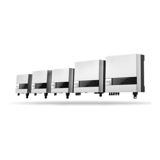
1. Overview Model Front View Bottom View CPS SC1.5KTL CPS SC2KTL CPS SC2.8KTL CPS SC4KTL CPS SC4KTL-O... - Page 9 Parts Description LCD Display: Showing the Display information switch inverter status Operation LED, Optional communications Green, normal slot: RS485 & others Operation LED, Red, fault status Utility (AC) connection: Solar panel input RS232 cover Terminal Block Edition 3.0E, 2011/05...
-
Page 10: Features
2. Features Very high conversion efficiency Automatic MPPT (Maximum Power Point Tracking) Higher power capacity than similar products of the same size. Embedded LCD display showing complete status information Natural convection cooling. Quiet, fan-less design ... -
Page 11: Installation Instructions
3. Installation instructions Opening the package After opening the package, please check the contents of the box. It should contain the following: One CHINT inverter Instruction manual One mounting frame 4 mounting screws 2 safety-lock screws One cable gland (PG21) for AC cable in CPS SC4KTL and SC4KTL-O One AC socket assembly in CPS SC1.5KTL,SC2KTL and SC2.8KTL... - Page 12 Check the ambient temperature of installation is within specified range -20 ~ +55C. The AC grid voltage is 230VAC, 50Hz. Electric utility company has approved the grid connection. Qualified personnel are performing the installation. Adequate convection space surrounds the inverter. ...
-
Page 13: Mounting Pv-Inverter To The Wall
Mounting PV-Inverter to the wall Select a wall or solid vertical surface that can support the PV-Inverter. PV-Inverter requires adequate cooling space. Allow at least 30cm space above and below the inverter. Using the mounting frame as a template, drill 4 holes as illustrated in the following figures. - Page 14 Hang PV-Inverter on the mounting frame. Check installation conditions. a) Do not install the PV-Inverter on a slanted surface. b) Check the upper straps of PV-Inverter and ensure it fits on to the bracket.
- Page 15 c) Insert safety-lock screws to the bottom leg to secure the inverter. Edition 3.0E, 2011/05...
-
Page 16: Connecting To The Grid (Ac Utility)
Connecting to the grid (AC utility) Measure grid (utility) voltage and frequency. It should be 230VAC, 50Hz, and single phase. Open the breaker or fuse between PV-Inverter and utility. For CPS SC1.5KTL, SC2.8KTL, SC2KTL, SC4KTL and SC4KTL-O, connect AC wires as follows: ... -
Page 17: Connect To Pv Panel (Dc Input)
Suggested cable width for AC wire Diameter Model Area (mm AWG no. (mm) 1.29 1.5 16 CPS SC1.5KTL / CPS SC2KTL 1.63 2.0 14 CPS SC2.8KTL 2.05 2.5 12 CPS SC4KTL / CPS SC4KTL-O Connect to PV Panel (DC input) Make sure the maximum open circuit voltage ) of each PV string is less than 500V 450V... -
Page 18: Checking
’ ’ Checking When the PV panels are connected and their output voltage is greater than 100 V but the AC grid is not yet connected, the message on the LCD display produce the following messages in order: “MODEL= CPS SCxxKTL-x”... -
Page 19: System Diagram
4. System Diagram The typical connection diagram for the entire PV system is shown in the following figure. PV Panel: Provide DC power to inverter PV-Inverter: Converts DC (Direct Current) power from PV panel(s) to AC (Alternating Current) power. Because the PV-Inverter is grid-connected it controls the current amplitude according to the PV Panel power supply. -
Page 20: Operation Of Pv-Inverter
5. Operation of PV-Inverter Initialization for Regulation Setting The Inverter provides a “Initialization” function at the first time start-up as an process in which user is able to select the intended regulation type before normal operation. The inverter will not able to operate normally before regulation setting is completed even though it is connected correctly at both DC input and AC output. -
Page 21: Modes Of Operation
Initialization Press button (1sec) VDE0126-1-1 “INIT OK” indicate Regulation type setting is completed Press button (1sec) INIT OK RD1663 Press button (5sec) to set Press button (1sec) intended Regulation type ENEL Guide 2010 Press button (1sec) Only appear on relevant model Press button (1sec) Only appear on G83/1-1... -
Page 22: Front Panel Arrangement
3. Shutdown mode: During periods of little or no sunlight, inverter automatically stops running. In this mode, inverter does not take any power from the grid. The display and LED’s on the front panel do not work. Front Panel arrangement... -
Page 23: Front Panel
Front Panel Operating PV-Inverter is quite easy. During normal operation, the inverter runs automatically. However, to achieve maximum conversion efficiency of inverter please read the following information: Automatic ON-OFF: PV-Inverter starts up automatically when DC-power from the PV panel is sufficient. Once the PV-Inverter starts it enters one of the following 3 states: ... - Page 24 information. Each subsequent press changes the display. The display sequence is shown in panel LCD display sequence figure on next page. Hold display: If you want to hold a specific display. Repeatedly press the function key until the desired display is reached. Release the key and press again for more than 1 second until you see “Lock”, release the key;...
-
Page 25: Lcd Display Sequence
LCD Display Sequence LCD display sequence Feeding wattage Model information Pac=xxxx.xW Model=xxxxxx F/W version Turn-on backlight Cx.xx Feeding energy of Operating status Etoday=xx.xxkWh Normal State the current day Contrast Adj. Eac=xx.xkWh Contrast Accumulate energy. DC-PV voltage Language setting Vdc =xxx.xV Set Language Grid voltage Feeding current... -
Page 26: Auto Test Setting (Only For Enel Guide 2010 Model)
Auto Test Setting (Only for ENEL GUIDE 2010 model) The Inverter is supplied with an auto test function which enables the user to check that the protection interface is operating correctly. In order to select this function, press the function button until the message "AUTO TEST SET" appears on the display panel. - Page 27 Auto Test If the threshold and the grid voltage are equal, the PV Inverter switches to fault. Display shows a message similar to this switch-off time OK. Upper frequency threshold will be checked. Display shows variation between upper frequency threshold and mains supply.
- Page 28 Auto Test If all the above tests have been performed, the display shows the message TEST PASSED. PV Inverter switches to normal operation mode. If one of the above tests failed, the display shows the message AUTO TEST FAILED. PV Inverter switches automatically and permanently to fault status.
-
Page 29: Auto Test Record (Only For Enel Guide 2010 Model)
Auto Test Record (Only for ENEL GUIDE 2010 model) After the Auto test setting, inverter will record the test result values, as shown in below. **Press the button for 5 seconds, the messages shown on the screen will change per second. Un-press the button, the Auto Test Record will be shown on the screen. -
Page 30: Accuracy Of The Reading
Maximum Power Point Tracking (MPPT) A good PV inverter must be Maximum power point 1000W/m @ 1000W/m ~ 120W able to convert the maximum 800W/m power from any PV panel. Due 600W/m to its advanced design, this PV-Inverter track maximum power from your PV panel in any condition. -
Page 31: Inverter Status
6. Inverter Status This inverter is designed to be user-friendly; therefore, the status of the Inverter can be easily understood by reading the information shown on the front panel display. All possible messages are shown in the following table. Display information Operating In English In German... - Page 32 Operating In English In German In Italian Description conditions FLASH FLASH FLASH FLASH FLASH firmware Monitoring Parameters Instantaneous Output Pac=xxxx.xW Pac=xxxx.xW Pac = xxxx.xW The real time output power in xxxx W power Accumulated energy Total energy to has been fed to grid since Eac = xxxxxxkWh Eac = xxxxxxkWh E = xxxxxxkWh...
- Page 33 Operating In English In German In Italian Description conditions System Fault Earth fault of the PV-panels or failure of surge Isolation failure Isolation fault Isolationsfehler Err.Isolamento voltage protection Leakage current on ground conductor is too GFCI active Ground I fault Fehlerstrom I dispers.Alta high...
- Page 34 Operating In English In German In Italian Description conditions The relay between inverter and grid is not Output relay failure Relay Failure Relaisfehler Err.relè functional Output DC injection too DC INJ High DC INJ zu hoch Idc uscita alta Output DC injection too high high EEPROM problem EEPROM Failure...
- Page 35 Operating In English In German In Italian Description conditions System Information CPS SC1.5KTL / CPS SC1.5KTL / CPS SC1.5KTL / Model display Inverter model name CPS SC2KTL / … CPS SC2KTL / … CPS SC2KTL / … LCD contrast Contrast Kontrast Contrasto The top menu of LCD contrast setting...
-
Page 36: Led
There are 2 LED’s on the inverter, one is green and the other is red. Normally, only the green LED switches on during operation. Their indicated status is explained as follows: Power on (green LED): It lights to indicate that the inverter is running. -
Page 37: Communications
7. Communications This inverter is equipped with a powerful communications interface and options. Use “Pro Control” to monitor the status of your PV-Inverter. Also, qualified personnel can upgrade the firmware using the RS232 port. RS232: To use the RS232 port, remove the RS232 cover on the bottom side of the inverter. -
Page 39: Trouble Shooting
8. Trouble shooting In most situations, the inverter requires very little service. However, if inverter is not able to work perfectly, please refer to the following instructions before calling your local dealer. Should any problems arise, the red (Fault) LED on the front panel turns on and the LCD displays the relevant information. - Page 40 1. The internal temperature is higher than specified normal value Over 2. Find a way to reduce the ambient temperature. temperature 3. Or move the inverter to a cooler environment 4. If it is not effective, call local service Relay Failure DC INJ High EEPROM 1.
-
Page 41: Specifications
9. Specifications Model SC1.5KTL SC2KTL SC2.8KTL SC4KTL SC4KTL-O Germany (DE) Italy (IT) Market United Kingdom (UK) China (CN) Input (DC) Nominal DC voltage 360 V 400 V Max. PV open voltage 450V 500V System start-up voltage Typical 120 V Initial feeding voltage 150 V Shutdown voltage Typical 70V... - Page 42 Model SC1.5KTL SC2KTL SC2.8KTL SC4KTL SC4KTL-O DC insulation resistance > 5M Output (AC) Nominal AC power 1500W 2000W 2800W 4000W 4000W Max. AC power (in 10 minutes) 1650W 2200W 3000W 4400W 4400W Nominal AC current 6.6 A 8.7 A 12.2 A 17.4 A 17.4 A Max.
- Page 43 Model SC1.5KTL SC2KTL SC2.8KTL SC4KTL SC4KTL-O Disconnection time of ≦0.2 sec. excess operational frequency range Re-connecting time after 30 sec disconnection Operational voltage range 190~267V (F/W Setting) Disconnection time of excess operational voltage Min Voltage protection 0.2 s; Max voltage protection 0.1s range for Italy Operational frequency...
- Page 44 Model SC1.5KTL SC2KTL SC2.8KTL SC4KTL SC4KTL-O for United Step1 : 207~246V Operational voltage range 212~256V Kingdom S tep2 : 189~256V (F/W Setting) (UK) U/V st1 200.1V(87%), 2.5s Disconnection time of O/V st1 253V(110%), ≦1.5 sec. excess operational voltage U/V st2 184V(80%), 0.5s range O/V st2 264.5V(115%), 0.5s...
- Page 45 Model SC1.5KTL SC2KTL SC2.8KTL SC4KTL SC4KTL-O Re-connecting time after 180 sec 180 sec disconnection Efficiency Max. conversion efficiency European efficiency Edition 3.0E, 2011/05...
-
Page 46: Typical Efficiency Charts Vs. Load
Typical Efficiency Charts vs. Load CPS SC1.5KTL CPS SC2KTL CPS SC2.8KTL CPS SC4KTL / CPS SC4KTL-O... -
Page 47: Disposal
10. Disposal The dealer or installers should remove the PV Inverter from the array and contact the supplier for disposal instructions The inverter must not be disposed of with the household waste. Dispose of the PV Inverter at the end of its service life should be done in accordance with the disposal regulations for electronic waste which apply at the installation site at that time. -
Page 48: Contact Information
11. Contact Information Should you have technical problems concerning this product, please contact our Service line. We require the following information in order to provide you with the necessary assistance: • Inverter type • Serial number of the PV Inverter •... -
Page 49: Regulation & Certificate
12. Regulation & Certificate Regulatory Type SC1.5KTL SC2KTL SC2.8KTL SC4KTL SC4KTL-O VDE0126-1-1 ENEL Guide Grid 2010 Monitoring G83/1-1; G83/1-1 G83/1-1 G83/1-1 G59 issue2 G59 Issue 2 Safety DIN EN 50178 (4.98) (VDE0160) (IEC62103) EMC: EN 61000-6-2 EMS / EMI EN 61000-6-3 LVD: 2006/95/EC EMC: 2004/108/EC Edition 3.0E, 2011/05... -
Page 50: Vde Certificate (European Models)
VDE Certificate (European models)
Need help?
Do you have a question about the CPS Series and is the answer not in the manual?
Questions and answers