Table of Contents
Advertisement
Quick Links
Advertisement
Table of Contents

Subscribe to Our Youtube Channel
Related Manuals for CHNT Power CPS SCA-T1 Series


Summary of Contents for CHNT Power CPS SCA-T1 Series
- Page 1 Edition:1.0.0 USER MANUAL CPS SCA-T1 Series Grid-tied PV Inverter...
- Page 2 History Preface About This Manual VERSION VERSION ISSUED ISSUED COMMENTS COMMENTS This manual describes the installation, electrical connection, commissioning and maintenance, APP 11-Nov-22 First release operation of the inverter. Please first read the manual and related documents carefully before using the product and store it in a place where installation, operation and maintenance personnel can access it at any time.
-
Page 3: Table Of Contents
CONTENTS 6. Startup/Shutdown Procedure Preface 6.1 Check before startup/shutdown procedure About This Manual Target Group 6.2 Startup Procedure Scope 6.3 Shutdown Procedure Conventions 7. Commissioning 1. Safety 7.1 Inspection 7.2 Commissioning Procedure 1.1 Symbols Used 8. User Interface 1.2 Safety Instruction 8.1 LED Indicator 2. -
Page 4: Safety
Safety Safety 1. Safety Before using the inverter, please read all instructions and cautionary markings on the unit and manual. 1.2 Safety Instruction Put the instructions where you can take them easily. Installation and maintenance of inverters must be performed by qualified personnel, in accordance with The inverter of us strictly conforms to related safety rules in design and test. -
Page 5: Product Introduction
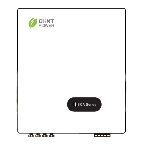
Product Introduction Product Introduction 2. Product Introduction 2.1 Overview 2.3 Product Appearance This series inverter is an important part of PV system and it is suitable for household use, commercial The following is only for reference, specific please in kind prevail. use, fishery use, agricultural use and other scenarios. -
Page 6: Unpacking And Storage
Product Introduction Unpacking and Storage 3. Unpacking and Storage 3.1 Unpacking and Check Complete test and strict inspection shall be done before the inverter is sent out. When receiving the inverter, check that the packing materials are intact. After unpacking, examine the PV inverter and its fittings for damage and check that the deliverables are complete. -
Page 7: Storage Inverter
Unpacking and Storage Installation Installation 3.2 Storage Inverter After checking the outer packing, move the PV inverter to the designated installation position horizontally. If the inverter is not used immediately, please keep the inverter in a specific environment according to the following requirements: 1. - Page 8 Installation Installation 4.1.2 Mounting Requirements Installation perspective schematic Mount the inverter vertically or tilted backward by max 15°. In order to facilitate the heat dissipation of the inverter. The wrong installation mode causes the inverter to be damaged or unable to NOTICE work properly.
-
Page 9: Mounting
Installation Installation 4.2 Mounting Step 1. Install the mounting bracket Step 2. Install the inverter. Install the inverter on the bracket accurately and tighten the screws at both sides, as shown in Step 5 and 1.The walls must be fileproof and non-flammable materials, othewise there is a fire Step 6. -
Page 10: Electrical Connection
Electrical Connection Electrical Connection 5. Electrical Connection Grounding According to the EN50178 requirement, the right side of the device has a protective grounding connection. System Connection Be sure to connect the protection ground cable to this port when installing the inverter. The user can perform the ground connection according to the on-site condition. -
Page 11: Ac Connection
Electrical Connection Electrical Connection 5.2 AC Connection 5.2.1 AC cable connection Torque 1. Measure and access the voltage and frequency of the point to ensure that it meets the grid-tied 5K-15K 5.5N.m ② specifications of the inverter. 17K-25K 12N.m 2. PE wire (GND) must be well grounded to ensure that impedance between Neutral wire and Earth wire is less than 10Ω. -
Page 12: Dc Connection
Electrical Connection Electrical Connection 5.3 DC Connection Before connecting the PV input to the inverter, ensure that the package meets the following PV modules generate electric energy when exposed to sunlight and can create an electrical electrical specifications. shock hazard. Therefore, when connecting the PV modules, shield them with opaque cloth and ensure that DC switches are OFF. -
Page 13: Communication Connection
Electrical Connection Electrical Connection 5.4.2 RS485 Connection 5.3.2 PV Connection Note: RS485 is only applicable to data logger or other device you use. Skip this part if you use wifi monitoring. PV connection please refer to below. 8~10mm Positive Connector Click Limit buckle Diameter... -
Page 14: Power Limit
Electrical Connection Electrical Connection 5.5 Power limit 5.4.3 Country code configuration (only for Administrator) Enabling Bluetooth communication on your mobile phone, you can set parameters about power limit Click "INV/ESI settings" button to enter the "Inverter Settings" page. Click "Initial" button to set grid code, function to control inverter. -
Page 15: Drm Connection
Electrical Connection Startup/Shutdown Procedure 5.6 DRM Connection When “Power limit function” is set to “Digital Power Meter”, the RS485 of inverter will change to a Host that will communicate with digital meter using ModbusRTU Protocol (9600 BPS, 8 data bit, 1 stop In accordance with AS/NZS 4777.2:2020, the inverter should support DRM( Demand Response bit, no parity data format) through communication address 1. -
Page 16: Startup Procedure
User Interface User Interface 6.2 Startup Procedure 7. Commissioning Startup the inverter following the procedures: It is necessary to make a complete commissioning of the inverter system. This will essentially protect Supply Main Switch the system from fire, electric shock or other damages or injuries. See if there’s any on site (The figure is only for reference) 7.1 Inspection... - Page 17 User Interface User Interface If the Inverter is malfunctioning, a samll horn symbol will appear in the APP interface. You can get specific LED status Explanation fault information by clicking on the small horn symbol as below image. Red/green/blue light 1.
-
Page 18: Bluetooth Connection Setting
User Interface Troubleshooting and Maintenance 8.2 Bluetooth Connection Setting Troubleshooting and Maintenance 1. Scan the QR code to download "Chint Connect" APP. Before maintaining and commissioning inverter and its peripheral distribution unit, Note: You need to grant all access rights in all pop-up windows when installing the APP or Chint setting your phone. - Page 19 Troubleshooting and Maintenance Troubleshooting and Maintenance 1. If the alarm occurs accidentally, possibly the power grid is abnormal accidentally. No extra 1. If the alarm occurs occasionally, the inverter can be automatically recovered. No action is required. C0-Internal power action is needed. 2.
-
Page 20: Maintenance
Troubleshooting and Maintenance Troubleshooting and Maintenance Fan Maintenance 1. If the alarm occurs occasionally, the inverter can be automatically recovered. No action is required. CF-Inverter When the external fan of the inverter can’t work normally, the inverter may not cool effectively. 2. -
Page 21: Technical Specifications
Technical Specifications Technical Specifications Technical Specifications MODEL MODEL CPS SCA5KTL-T1/EU CPS SCA6KTL-T1/EU CPS SCA8KTL-T1/EU CPS SCA10KTL-T1/EU CPS SCA10KTL-T2/EU CPS SCA12KTL-T1/EU CPS SCA15KTL-T1/EU Input(PV) Input(PV) Max. PV configuration (STC1) 150% Max. PV configuration(STC1) 150% Max. PV power voltage (V) 1100V Max. PV power voltage (V) 1100V Rated input voltage (V) 620V... - Page 22 Technical Specifications Technical Specifications MODEL PV 17KTL-D3/G2 PV 20KTL-D3/G2 CPS SCA15KTL-T2/EU CPS SCA17KTL-T1/EU CPS SCA20KTL-T1/EU MODEL CPS SCA22KTL-T1/EU CPS SCA25KTL-T1/EU Input(PV) Input(PV) Max. PV configuration (STC1) 150% Max. PV configuration (STC1) 150% Max. PV power voltage (V) 1100V Max. PV power voltage (V) 1100V 620V Rated input voltage (V)
- Page 23 : Tel +86 21 3779 1222-6300 : Fax+86 21 3779 1222-6003 : : Emailservice.cps@chint.com Add:Block 4, 3255 Sixian Road, SongJiang District, Shanghai, P.R. China...
Need help?
Do you have a question about the CPS SCA-T1 Series and is the answer not in the manual?
Questions and answers