Table of Contents
Advertisement
Quick Links
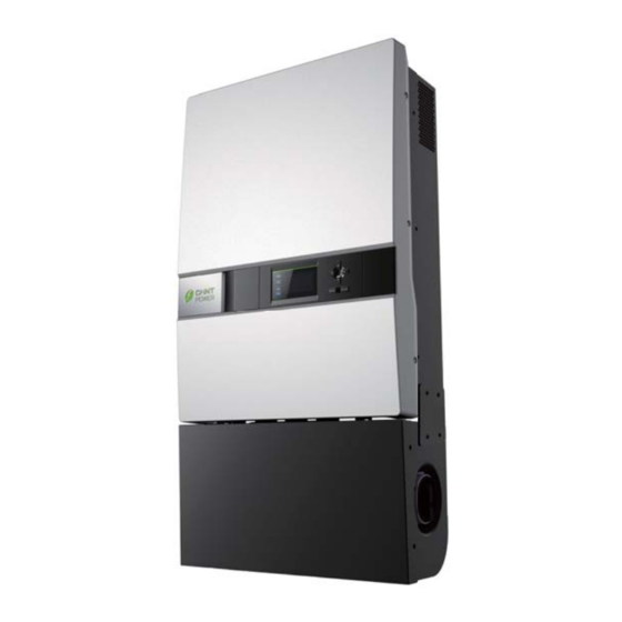
20kW Grid-tied PV Inverter for North America
The CPS SC20KTL-DO/US-480 grid-tied PV inverter is a tranformerless,
three phase product designed for the North America market in
compliance with UL and CSA standards. Patented 3-level control
algorithm and thermal design provide 97.3% maximum efficiency.
CPS SC20KTL-DO/US-480 features small size, light weight and high
power density. Multi flexible mounting modes make installation and
maintenance easy and quick. The enclosure of the inverter is rated
NEMA 3R (IP65) for general purpose outdoor applications. Enhanced
DSP control, comprehensive protection functions and advanced thermal
design enable a high reliability product with optional warranties up to 20
years.
Efficiency Curve
High Efficiency
Maximum efficiency of 97.3%, CEC efficiency of 96.5%
3-level technology and enhanced control mechanism to
achieve high efficiency over wide load range
High speed and precise MPPT algorithm
2 MPP trackers to achieve higher system efficiency
Transformerless design
High Reliability
Standard warranty: 5 years, extention up to 20 years
Design for reliability
Comprehensive protection functions
Enhanced DSP system
Advanced thermal design, with variable speed fans
Anti-Islanding protection
Ground-fault detection and interruption circuit
Redundant controller for system protection
SHANGHAI CHINT POWER SYSTEMS CO., LTD. All rights reserved.
Specifications and designs included in this datasheet are subject to change without notice.
CHINT POWER 2012/08-MKT
MPPT VOLTAGE
Broad Adaptability
NEMA 3R (IP65), outdoor application
Multi mounting modes, quick installation and
easy maintenance
High altitude application
Integrated DC (+, -) and AC disconnect
Wide MPPT range enables flexible stringing
Light weight, compact design for commercial rooftops
Dimensions
700 International Pkwy, Suite 102, Richardson, TX 75081
Tel: 855-584-7168
Mail: AmericaSales@chint.com
Datasheet
Chint Power Systems America
Web: www.chintpower.com/na
Advertisement
Table of Contents

Subscribe to Our Youtube Channel
Related Manuals for CHNT Power CPS SC Series


Summary of Contents for CHNT Power CPS SC Series
- Page 1 Datasheet 20kW Grid-tied PV Inverter for North America The CPS SC20KTL-DO/US-480 grid-tied PV inverter is a tranformerless, three phase product designed for the North America market in compliance with UL and CSA standards. Patented 3-level control algorithm and thermal design provide 97.3% maximum efficiency. CPS SC20KTL-DO/US-480 features small size, light weight and high power density.
- Page 2 Technical Data Model Name CPS SC20KTL-DO/US-480 DC Input Max. PV Power 27kW Nominal DC Input Power 21kW Max. DC Input Voltage 600Vdc Operating DC Input Voltage Range 260-580Vdc Start-up DC Input Voltage / Power 300V / 200W Nominal DC Input Voltage 500Vdc Number of MPP Trackers MPPT Voltage Range...
- Page 3 CPS SC Series Grid-tied PV Inverter CPS SC20KTL-DO/US-480 Installation and Operation Manual CHINT POWER SYSTEMS AMERICA CO., LTD.
-
Page 4: Table Of Contents
Table of Contents Before You Start… ............1 Chapter 1 IMPORTANT SAFETY INSTRUCTIONS..2 Chapter 2 Overview .............4 2.1 Inverter for grid-tied PV systems ......4 2.2 Product type description ........4 2.3 Product features ..........5 2.4 Circuit structure design ........6 2.5 Appearance description ........6 Chapter 3 Installation...........8 3.1 Basic requirements ..........9 3.2 Mechanical installation ........10... - Page 5 4.4 Fault shutdown ........... 38 Chapter 5 Human Machine Interface ......38 5.1 Description of LCD panel ........38 5.2 Operation state ........... 39 5.3 Interface and menu functions ......40 5.3.1 Interface types ........... 40 5.3.2 Main operation interface ......42 5.3.3 Operation information ........
-
Page 6: Before You Start
Before You Start… This manual contains important information regarding installation and safe operation of this unit. Be sure to read this manual carefully before using. Thanks for choosing this Grid-tied PV Inverter (referred to in this manual as “PV Inverter”, or simply “Inverter”). -
Page 7: Chapter 1 Important Safety Instructions
Chapter 1 IMPORTANT SAFETY INSTRUCTIONS (SAVE THESE INSTRUCTIONS) Please read this manual carefully before installation. CPS reserves the right not to guarantee the quality for equipment damage if the user fails to install the equipment as per the instructions in this manual. ELECTRIC SHOCK HAZARD: All operations and wiring should be performed by qualified technical personnel. - Page 8 avoid reducing conversion efficiency due to excessively high internal temperature of the machine. CAUTION: Steel conduits as the cable protector need to be prepared by the customers before installation. HIGH TEMPERATURE: Although designed to meet international safety standards, the PV-Inverter can become hot during operation. Do not touch the heat sink or peripheral surfaces during or shortly after operation.
-
Page 9: Chapter 2 Overview
Chapter 2 Overview 2.1 Inverter for grid-tied PV systems CPS SC20KTL-DO/US-480 inverter can be applied to various commercial rooftop systems and distributed power station systems. Normally, the system mainly consists of PV modules, DC power distribution equipments, PV inverter and AC power distribution equipments (Figure 2-1). -
Page 10: Product Features
2.3 Product features CPS SC20KTL-DO/US-480 inverter incorporates the advanced 3-level and MOSFET paralleled with IGBT technology to minimize the energy loss. The two-MPPT design has the benefit of increasing the power generating efficiency of the whole PV system. The inverter has 2 MPPTs, so a separate array can be controlled by an independent Maximum Power Point Tracking (MPPT) control circuit. -
Page 11: Circuit Structure Design
2.4 Circuit structure design basic schematic diagram SC20KTL-DO/US-480 is shown in Figure 2-2. The input DC passes through lightning-proof circuit, DC EMI filter, and the boost circuit to achieve maximum power tracking and boost up voltages. The inverter converts the DC energy to 3-phase AC energy. - Page 12 Description main items SC20KTL-DO/US-480 (shown in Figure 2-3): 1、LCD key buttons: operate the functions and change settings of inverter 2、LCD display: indicates data 3、LED indicator lights: indicate the status of inverter 4、DC input (4), AC output & ground terminals (1) and signal port (1) from left to right 5、DC switch: control the DC power on and off 6、AC switch: control the AC power on and off...
-
Page 13: Chapter 3 Installation
Chapter 3 Installation Below is the installation instruction of the inverter. Please read carefully and install the product step-by-step. 1. CPS SC20KTL-DO/US-480 Check and make sure that the following items are included in the package before installation, as shown in Table 3-1. -
Page 14: Basic Requirements
bolts & nuts pairs for backup use) for grounding wire (1 nut M5 nut for backup use) Ring terminal for grounding wire 16 for input wires, 3 for Cord end terminals output wires, 1 for neutral wire (optional) RJ45 connecters for communication cables for inverter with 1 MPPT Red wire... -
Page 15: Mechanical Installation
Sufficient convection space; Away from flammable and explosive substances. 3.2 Mechanical installation (1) Dimensions The dimensions of CPS SC20KTL-DO/US-480 inverter are shown in Figure 3-1. Figure 3-1 Dimensions of CPS SC20KTL-DO/US-480 (2) Check whether the place to mount the inverter is appropriate: (a) It’s better to mount the inverter in a vertical position. - Page 16 (c) Do NOT mount the inverter forwards. (d) Do NOT mount the inverter in a horizontal position. (e) Do NOT mount the inverter upside down. Figure 3-2 Mounting the inverter properly (3) Space required for inverter mounting on the wall (as shown in Figure 3-3) The distances between the inverter and the surrounding Chapter 3 Installation...
- Page 17 objects should meet the following conditions: two sides from the walls ≥11.81 inches; top distance ≥11.81 inches; bottom distance ≥23.62 inches; the minimum spacing between two inverters in parallel ≥11.81 inches. Figure 3-3 Inverter mounting dimensions (3) Secure the bracket with bolts through the mounting holes and install the inverter: (a) Mark the 6 bolt holes for mounting the bracket as shown in Figure 3-4;...
- Page 18 Figure 3-4 Bracket mounting dimensions (b) Drill holes at the marked positions with a diameter of 0.4 inch drill and put the 6 M8*25 expansion bolts into the holes; (c) Take the mounting bracket out of the package and secure the bracket on the wall with the 6 nuts in pair as shown in Figure 3-5;...
- Page 19 Figure 3-5 Positions of bolt holes on the bracket (d) Screw off the bolts and remove the two panels on both sides of the inverter as shown in Figure 3-6; Figure 3-6 Removal of panels before mounting inverter (e) Two people grab at the position on each side, lift up the inverter and then hang it on the bracket (Figure 3-7a~e).
- Page 20 Hand Grab Figure 3-7a Mounting inverter on the bracket Figure 3-7b Mounting inverter on the bracket Chapter 3 Installation...
- Page 21 Figure 3-7c Mounting inverter on the bracket Figure 3-7d Mounting inverter on the bracket Chapter 3 Installation...
- Page 22 Figure 3-7e Mounting inverter on the bracket (f) Put the two removed panels back and secure them with 4 M4*12 bolts on each side, as shown in Figure 3-8. Figure 3-8 Securing panels on both sides Chapter 3 Installation...
-
Page 23: Electrical Installation
3.3 Electrical installation CAUTION: Steel conduits as the cable protector need to be prepared by the customers before installation. Inverter cable terminals of CPS SC20KTL-DO/US-480 are shown in Figure 3-9: DC input AC output and ground Signal port Figure 3-9 Inverter cable terminals The 5 ports on the left are for DC input, AC output and ground connections, matching the 1¼... - Page 24 under any conditions; (b) The inverter has 2 MPPTs. Ensure that the Max. DC input current of each MPPT does NOT exceed 35A. (c) Confirm that the PV modules for each MPPT of the inverter are of the same types and specifications before connection.
- Page 25 16~10 strings 16~10 strings PV1+ IN1+ PV1- IN1- 14~10 Inverter strings PV2+ IN2+ PV2- IN2- Note 1 : The DC fuse protectors of different fusing capacity should be chosen according to the short circuit current of PV modules. The 600VDC Littelfuse KLKD fuse series are recommended.
- Page 26 The recommended fuse types are listed in the following table: Table 3-4 Recommended fuse types DC input 2 strings/MPPT 3 strings/MPPT 4 strings/MPPT Fuse KLKD 30 KLKD 15 KLKD 15 Note 2: Concerning the current share of fuse for each DC input string, 1 or 2 DC input strings are NOT recommended.
- Page 27 (b) Insert the cables through steel conduits and strip the skin 0.4 inch off the cables as shown in Figure 3-10: Figure 3-10 Diagram for wire stripping of DC input (c) Crimp the terminal as shown in Figure 3-11: Figure 3-11 Diagram for terminal crimping of DC input (d) The order of wire connection from left to right is PV1-, PV1+, PV2-, PV2+.
- Page 28 Figure 3-12 Diagram for wire connection of DC input (e) For the inverter with 1 MPPT working alone, connect J1 (IN1+) with J3 (IN2+) wire socket (in the Wiring box) through the red wire in the accessory kit; Connect J2 (IN1-) with J4 (IN2-) wire socket through the black wire in the accessory kit, as shown in Figure 3-13: Chapter 3 Installation...
-
Page 29: Ac And Ground Connection
Figure 3-13 Diagram of wire connection in the Wiring box for inverter with 1 MPPT working alone 3.3.2 AC and ground connection The following describes how to connect the AC output and grounding cables between the inverter and the public power grid: (1) Use the recommended cables: L1 (Line 1), L2 (Line 2), L3 (Line 3), Neutral and Gnd... - Page 30 Figure 3-14 Diagram for wire stripping of AC output (c) Crimp the terminal as shown in Figure 3-15: Figure 3-15 Diagram for terminal crimping of AC output (d) Connect the L1, L2, L3 and Neutral (red, black, blue, grey) AC output wires to the corresponding terminals on the PCB board.
-
Page 31: Communication Connection
accessory kit as shown in Figure 3-17: Figure 3-17 Diagram for terminal crimping of grounding conductor (c) Connect the Gnd wire with a M5 nut at the marked place on the lower right side of the Wiring box, as shown in Figure 3-18: Figure 3-18 Diagram for wire connection of AC output and Grounding 3.3.3 Communication connection There are two RS485 signal ports on the inverter. - Page 32 (1) The communication of one single local inverter is to connect the RS485 communication bus cable through the RS485-1 or RS485-2 port of the inverter directly. Wiring requirement of RS485-1/2 is shown in Table 3-6: Table 3-6 RS485-1/2 wiring requirement Color Function White orange...
- Page 33 RS485-2 port of one inverter to the RS485-1 port of another inverter and then connect to the data logger through the RS485 communication bus cable. The Figure 3-20 shows how to connect the inverters to the datalogger. For more information about CPS monitoring solutions, please contact our after-sales service center.
-
Page 34: Chapter 4 Operation
Chapter 4 Operation 4.1 Start-up and shut-down 4.1.1 Start-up Manual start-up: Manual start-up is required after initial installation or manual (fault) shut-down. Move the cursor from the main operation interface to “4 Setting”. Press ENTER and go to submenu “1 ON/OFF”. Then move the cursor to “ON”... -
Page 35: Operation Mode
or the ambient temperature exceeds the normal range. 4.2 Operation mode There are 4 operation modes. The following are corresponding indications for each mode. (1) System check mode for start up, as shown in Figure 4-1: Figure 4-1 System self check ongoing This mode indicates that the inverter is checking whether it is ready for normal operation after the manual start-up of the inverter. - Page 36 In this mode, the inverter converts the power generated by PV modules to AC continuously and feeds into the power grid. (3) Standby mode, as shown in Figure 4-3: The inverter will turn into standby mode when the output voltage and power of PV modules do not meet the startup conditions or PV voltage and input power are lower than the set point.
-
Page 37: Grid Connection And Power Generation
Figure 4-4 Fault indication interface ELECTRIC SHOCK HAZARD: All operations and wiring should be performed by qualified technical personnel. Disconnect the inverter from PV modules and the Power Grid before the maintenance and operation of the equipment. 4.3 Grid connection and power generation The grid connection and power generation process of CPS SC20KTL-DO/US-480 is automatic. - Page 38 4.4 Fault shutdown The inverter will be shut down automatically when the PV power generation system fails, such as output short circuit, grid overvoltage / undervoltage, grid overfrequency / underfrequency, high ambient temperature or internal malfunction of the machine. The causes of fault can be identified based on the faults listed in Table 4-1.
- Page 39 Alarm/ Recommended Protection/ Definition Possible causes solutions Fault then reboot the system; 3、Contact after-sales service personnel 1、Observe for 5 minutes and see whether the alarm will be eliminated 1、Fan is blocked; automatically; 2、Fan service life The visible fan from 4、 2、Check for foreign has expired;...
- Page 40 Alarm/ Recommended Protection/ Definition Possible causes solutions Fault service personnel 1、Observe for 10 minutes and see whether the alarm will 1、Grid voltage is be eliminated abnormal; automatically; Power grid breaks 2、Check whether the down grid voltage is within the 2、 Grid voltage exceeds 2、Cable specified range;...
- Page 41 Alarm/ Recommended Protection/ Definition Possible causes solutions Fault switch, wait for 5 minutes, and then turn on the switch again; 4、Contact after-sales service personnel 1、Check whether PV positive pole positive pole and 5、PV1 (2) PV module is and negative pole negative pole are Reverse* connected inversely...
- Page 42 Alarm/ Recommended Protection/ Definition Possible causes solutions Fault 1、The inverter can be forced to restart once if it is required by Internal fault of the Fault occurs inside operation and if it is Fault IntFaultA~O inverter the inverter confirmed that there is no other problem;...
-
Page 43: Fault Shutdown
Chapter 5 Human Machine Interface 5.1 Description of LCD panel The CPS SC20KTL-DO/US-480 LCD panel mainly consists of LCD screen, LED indicator lights, buzzer and 6 keys, as shown in Figure 5-1. Figure 5-1 LCD panel Meanings of indicator lights are shown in Table 5-1 and functions of the keys are shown in Table 5-2. -
Page 44: Operation State
Light In other operation state or no working power supply Light Grid is normal Grid state Grid abnormal (light up 0.5s, light GRID Blink indicator light out 1.6s) Light No working power supply Light Fault occurs Slow Alarm occurs (light up 0.5s, light off blink Fault state FAULT... -
Page 45: Interface And Menu Functions
that the system is energized and under DSP control when “POWER” lights up. “RUN” will light up when the inverter detects that the grid connection conditions meet the requirements and power is fed into the grid. “RUN” will blink if the grid is in derated running state during the period of feeding power into the grid. - Page 46 Figure 5-2 LOGO interface (2) Indication of inverter operation mode: Figure 5-3 Inverter system check ongoing Figure 5-4 Inverter system in standby mode Chapter 5 Human Machine Interface...
-
Page 47: Main Operation Interface
Figure 5-5 Default display interface for normal operation Figure 5-6 Fault indication interface LCD screen will display different mode interfaces based on the operation modes of the inverter. There are four operation modes: startup system check mode (as shown in Figure 5-3), stand-by mode (as shown in Figure 5-4), normal operation mode (as shown in Figure 5-5, the switching time between (a) and (b) is 5 seconds), and fault mode (as shown... -
Page 48: Operation Information
Figure 5-7. 1 O P . In fo 2 A la rm 3 H isto ry → 4 S ettin g Figure 5-7 Contents indicated on the main operation interface The main operation interface of LCD screen has 4 level-1 menus, i.e. “1 OP. Info”, “2 Alarm”, “3 History” and “4 Setting”. -
Page 49: Present Fault
Figure 5-8 Operation information indication 5.3.4 Present fault As described before, when faults occur during the normal operation of the inverter, corresponding fault message will be indicated in “2 Alarm” menu besides the sound and light alarms. Move the cursor to “2 Alarm” and press ENTER to check out the specific fault information, as shown in Figure 5-9. -
Page 50: History
If not exiting No Alarm 2 Alarm SPICommErr Else exiting IntProtectA … Figure 5-9 Present fault information 5.3.5 History Move the cursor to “3 History” in the main interface. Press ENTER to check the history information, as shown in Figure 5-10. There are 4 submenus in “3 History” : “1 ErrRecd”, “2 OP. -
Page 51: System Setup
TotalTag” menu. Figure 5-10 History menu and submenu 5.3.6 System setup Move the cursor to “4 Setting” in the main interface. Press ENTER to set the current system parameters, as shown in Figure 5-11. There are 5 submenus in “4 Setting” : “1 ON/OFF”, “2 Language”, “3 Buzzer”, “4 SysTime”... - Page 52 screen ; move the cursor to “OFF” and press ENTER then “OFF State” will be indicated as well. The inverter will stand by instead of working normally if the startup conditions are not satisfied even “ON” is selected. The inverter will be shut down immediately if “OFF”...
-
Page 53: System Protection Parameter Setup
→ ON ON State 中文 → English 1 ON/OFF 2 Language 3 Buzzer 4 Setting →4 SysTime English Ver. 5 Commun. KeyBeep Enable AlarmBeep → Disabled ↓ 2009 / 12 / 15 21 :14 → Address BaudRate 3 1 2400 2 4800 3 9600 4 115200... - Page 54 Table 5-3 Protection Parameters Table Setup range (lower limit, default Description of parameter & upper limit) (200, 528, 533V) Grid line voltage upper limit Trip time under Max. Grid V. (0.05, 1.80, 2.00S) (0, 422, 480V) Grid line voltage lower limit (0.05,1.80,2.00S)...
- Page 55 This function will not respond when the inverter is in operation mode and a “FaultOperated” alarm interface will be indicated. (3) “3 Recover” menu, the manufacturer’s parameter default value can be restored when the inverter is not in operation mode. Otherwise, a “FaultOperated” will be prompted.
-
Page 56: Chapter 6 Service And Maintenance
Chapter 6 Service and Maintenance SC20KTL-DO/US-480 inverters maintenance-free. The following regular maintenance steps must nevertheless be carried out at regular intervals to ensure the inverter’s operation with optimal performance. HIGH TEMPERATURE: The inverter and peripherals can be hot after operation. Maintenance shall be performed 15 minutes after the DC and AC power are both switched off. - Page 57 (2) Disconnect the fan tray assembly from the inverter by unplugging the wire connectors as shown in Figure 6-2; Figure 6-2 Unplugging the wire connectors (3) Remove the 4PCS screws off the fan bracket as shown in Figure 6-3 and 6-4; (Tool: 0.12 inch Hexagon socket screw key) Figure 6-3 Unscrew the fan bracket on the left side Chapter 6 Service and Maintenance...
-
Page 58: Restoring Of Fan Tray Assembly
Figure 6-4 Unscrew the fan bracket on the right side (4) Pull out the fan tray assembly from the left side of inverter as shown in Figure 6-5; Figure 6-5 Pulling out the fan tray assembly (5) Use a dry cloth to clean the fan tray assembly to prevent dirt accumulating on it. - Page 59 Figure 6-6 Inserting the fan tray assembly (3) Hook the fan tray assembly inside the Main housing at the right end as shown in Figure 6-7; Figure 6-7 Hooking the fan tray assembly (4) Make sure the wire connectors reveal from the right hole and the bracket is well connected, as shown in Figure 6-8 and 6-9;...
- Page 60 Figure 6-8 Revealing the wire connectors Figure 6-9 Fan tray assembly well connected (5) Connect the fan tray assembly with the inverter by plugging the wire connectors as shown in Figure 6-10; Figure 6-10 Plugging the wire connectors (6) Fix the left side of fan bracket on the Main housing with 2PCS screws as shown in Figure 6-11;...
- Page 61 Figure 6-11 Fixing the fan bracket on the left side (7) Fix the right side of fan bracket on the Main housing with 2PCS screws as shown in Figure 6-12; (Tool: 0.12 inch Hexagon socket screw key) Figure 6-12 Fixing the fan bracket on the right side Chapter 6 Service and Maintenance...
- Page 62 (8) Put the two removed panels back and secure them on both sides as shown in Figure 6-13. (Tool: PH2 cross screwdriver) Figure 6-13 Securing panels on both sides Chapter 6 Service and Maintenance...
-
Page 63: Chapter 7 Technical Data
Chapter 7 Technical Data Model Name CPS SC20KTL-O/US-480 DC Input Max. PV Power 27kW Nominal DC Input Power 21kW Max. DC Input Voltage 600Vdc Operating DC Input 260-580Vdc Voltage Range Start-up DC Input 300V / 200W Voltage / Power Nominal DC Input 500Vdc Voltage Number of MPP Trackers... - Page 64 Max AC Output Current 27.3A Rated Output Frequency 60Hz Output Frequency Range 59.3-60.5Hz Power Factor >0.99 Current THD <3% AC Disconnection Type Switch System Topology Transformerless Max. Efficiency 97.3% CEC Efficiency 96.5% Stand-by / Night <20W / <2W Consumption Environment Protection Degree NEMA 3R Cooling...
- Page 65 Weight 132lbs / 63kg Safety Safety and EMC UL1741:2010, CSA-C22.2 NO.107.1-01, Standard FCC PART15 Grid Standard IEEE1547: 2003, IEEE1547.1: 2005 Note: Exceeding the rated voltage shown in “Max. DC Input Voltage” may cause permanent damage to the equipment. Chapter 7 Technical Data...
-
Page 66: Chapter 8 Limited Warranty
Chapter 8 Limited Warranty The warranty policy of this product is specified in the contract; otherwise, the warranty period is 5 years. For service, Chint Power Systems America will provide local support. For Warranty terms, please refer to the CPS America standard warranty policy in place at time of purchase. - Page 67 CHINT POWER SYSTEMS AMERICA CO., LTD. Address: 700 International Parkway, Suite 102 Richardson, Texas 75081 Service Hotline: 855-584-7168 Email: AmericaSales@Chint.com SHANGHAI CHINT POWER SYSTEMS CO., LTD. Headquarters: Building 4, No. 855, Wenhe Road, Songjiang District, Shanghai, China Tele: +86-021-37791222-6300 Fax: +86-021-37791222-6001 Website: www.chintpower.com CPS SC20KTL-DO/US-480 Installation and Operation Manual (PN: 9.0020.0038C0) is printed for the first time.
- Page 68 [Operation and Maintenance Manual] End of Manual SunEdison www.sunedison.com...
Need help?
Do you have a question about the CPS SC Series and is the answer not in the manual?
Questions and answers