
Subscribe to Our Youtube Channel
Related Manuals for CHNT Power CPS SCA-S Series


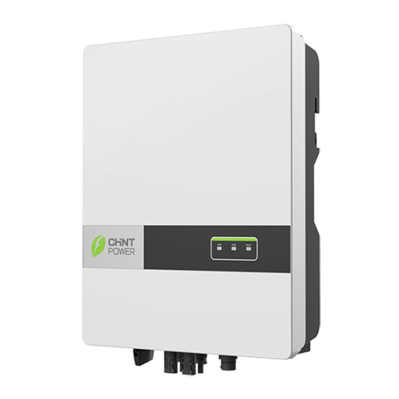
Summary of Contents for CHNT Power CPS SCA-S Series
- Page 1 CPS SC A-S/SM Series Grid-tied PV Inverter CPS SCA1/2/2.5/3/3.6KTL-S CPS SCA3/3.6/4/4.6/5/6KTL-SM Installation and Operation Manual Shanghai Chint Power Systems CO,.LTD...
-
Page 2: Table Of Contents
CPS SCA-S/ SM Series Inverter Contents Forward Application Model Intended Audience Symbol Conventions 1 Safety Precautions 1.1 Personnel Safety 1.2 The PV Inverter Protection 1.3 Installation Safety 1.4 Electrical Connections 1.5 Operating and Commissioning 1.6 Maintenance 1.7 Additional Information 2 Overview of the Inverter 2.1 Functional Models 2.1.1 Function 2.1.2 Model Description... - Page 3 CPS SCA-S/ SM Series Inverter 4.3.2 Compliance and Safety Symbols 4.4 Installation Requirements 4.4.1 Determining the Installation Position 4.4.2 Installation Mode Requirements 4.5 Installing a Rear Panel 4.6 Installing the Inverter 5 Electrical Connections 5.1 Connecting Protection Ground (PGND) Cables 5.1.1 Preparation 5.1.2 Wiring Procedures 5.2 Connecting AC Output Cables...
-
Page 4: Application Model
CPS SCA-S/ SM Series Inverter Forward Dear User, Thank you so much for your choosing 1K-6K, the latest generation of grid-tied PV Strings inverter (hereinafter referred to as the inverter) designed and developed by CHINT. This user manual introduces the inverter in terms of its installation, electrical connections, operation, commissioning, maintenance, and troubleshooting. -
Page 5: Symbol Conventions
CPS SCA-S/ SM Series Inverter Symbol Conventions Safety symbols used in this manual, which highlight potential safety risks and important safety information, are listed as follows: Symbol Description Indicates an imminently hazardous situation which, if not correctly DANGER followed, will result in serious injury or death. Indicates a potentially hazardous situation which, if not correctly WARNING followed, could result in serious injury or death. -
Page 6: Safety Precautions
CPS SCA-S/ SM Series Inverter 1 Safety Precautions Before beginning your journey, please read these safety precautions in User Manual carefully. 1.1 Personnel Safety a. The PV inverter must be installed, electronically connected, operated and maintained through specially trained technician; b. -
Page 7: Electrical Connections
CPS SCA-S/ SM Series Inverter 1.4 Electrical Connections Before installing the inverter, check all electrical ports to ensure no damage and no short circuit. Otherwise personal casualty and/or fire DANGER will occur. a. Input terminals of the PV inverter apply only to input terminals of PV String; do not connect any other DC source to the input terminals. -
Page 8: Additional Information
CPS SCA-S/ SM Series Inverter a. For personal safety, maintenance personnel must wear appropriate personal protective equipment (like insulation gloves and protective shoes) for the inverter maintenance. b. Place temporary warning signs or erect fences to prevent unauthorized access to the maintenance site. -
Page 9: Overview Of The Inverter
CPS SCA-S/ SM Series Inverter 2 Overview of the Inverter This chapter introduces the inverter and describes its functional model, network application, appearance, dimensions, and working process etc. 2.1 Functional Models 2.1.1 Function This series is a single-phase grid-tied PV string inverter (transformer less) that converts the DC power generated by PV strings into AC power and feeds the power into power grid. -
Page 10: Outline And Dimensions
CPS SCA-S/ SM Series Inverter PV strings inverter AC Distribution Unit low-voltage power grid Figure 2.2 Grid-tied PV system 2.3 Outline and Dimensions 2.3.1 Outline Figures 2.3 to 2.7 show the outline of the inverters as follows: Figure2.3 1K-3.6K PV Inverter with Single MPPT Input (unit: mm) 333.8 Figure2.4 3K-6K PV Inverter with Double MPPT Input (unit: mm) - Page 11 CPS SCA-S/ SM Series Inverter 1. Runing Indicator 2. COM Indicator 3. Fault Indicator Figure 2.5 The front view and amplification effect of LED indicator area 1K-3.6K PV Inverter with Single MPPT Input 3K-6K PV Inverter with Double MPPT Input Figure 2.6 The rear view of this series inverter 1.
-
Page 12: Working Process
CPS SCA-S/ SM Series Inverter 2.4 Working Process 2.4.1 Basic principle Description The 3K-6 PV i nverter with 2 MPPT input receives inputs from two strings of PV panel (1K-3.6K P nve t w h s ingle MPPT input receives inputs from only one sting of PV panel). -
Page 13: Working Modes
CPS SCA-S/ SM Series Inverter 2.5 Working Modes Three working modes of the inverter are shown as follows: standby, operating, and shutdown. Table 2.1 shows the conditions for the inverter to switch between working modes. Modes Description The PV inverter enters the standby mode when the input voltage of PV strings can enable auxiliary power supply to run,but cannot meet the inverter operation requirements. -
Page 14: Storage
CPS SCA-S/ SM Series Inverter 3 Storage This chapter describes the storage requirements for the inverter. The following storage instructions apply if the PV inverter will not be deployed immediately: Do not unpack the inverter (put desiccant in the original box if the PV inverter is unpacked). Store the PV inverter at a temperature range of -40℃... -
Page 15: Installation
CPS SCA-S/ SM Series Inverter 4 Installation Do not install the inverter on flammable building materials or in an DANGER area that stores flammable or explosive materials. Do not install the inverter in a place where personnel are likely to come into contact with its enclosure and heat sinks to avoid electrical CAUTION shock / burn. -
Page 16: Moving The Inverter
CPS SCA-S/ SM Series Inverter If any damage mentioned above is found, contact the dealer NOTICE immediately. 4.2 Moving the inverter After checking the outer packing, move the PV inverter to the designated installation position horizontally. Hold the handles on both sides of the inverter, as shown in Figure 4.2. Figure 4.2 Moving the inverter Do not place the PV inverter with its wiring terminals contacting the floor because the power ports and signal ports at the bottom of the... - Page 17 CPS SCA-S/ SM Series Inverter 4.3.2 Compliance and Safety Symbols Safety symbol Description Electrical shock! There are residual voltages in the PV inverter. It needs 10 minutes 10mins to finish discharge. The PV inverter must not be touched when in operation. Its enclosure and heat sinks are extremely hot.
- Page 18 CPS SCA-S/ SM Series Inverter The inverter must be installed in a well ventilated environment to ensure good heat dissipation. The inverter must be free from direct exposure to sunlight, rain, and snow to extend its service life. It is recommended that the inverter be installed in a sheltered place. If no shelter is available, build an awning, as shown in Figure 4.3.
- Page 19 CPS SCA-S/ SM Series Inverter >500 >500 >200 >200 >600 The lateral view The front view Figure 4.4 Installation Space Requirements (unit: mm) When installing multiple inverter, install them along the same line (as shown in Figure 4.5) if sufficient space is available, and install them in triangle mode (as shown in Figure 4.6) or in stacked mode (as shown in Figure 4.7) if no sufficient space is available.
- Page 20 CPS SCA-S/ SM Series Inverter Figure 4.6 Installation in triangle mode (unit: mm) Figure 4.7 Installation in stacked mode (unit: mm) The clearance between multiple inverters must be increased to NOTICE ensure proper heat dissipation when they are installed in a hot area.
- Page 21 CPS SCA-S/ SM Series Inverter 4.4.2 Installation Mode Requirements Install the inverter upright or at a maximum back tilt of 15 degrees to facilitate heat dissipation. Below are some correct / wrong installation modes, as shown in Figures 4.8&4.9. The correct installation mode upright Lean back Figures 4.8 The correct installation mode...
- Page 22 CPS SCA-S/ SM Series Inverter Step 1 Move out the rear panel from the packing case. Step 2 Determine the positions for drilling holes (as shown in Figure 4.10) using the rear panel. 3K-6K PV Inverter with two MPPT input 1K-3.6K PV Inverter with single MPPT input Figure 4.10 Determine the positions for drilling holes(unit:mm) Step 3 Level the hole positions using a level, and mark the hole positions using a marker...
- Page 23 CPS SCA-S/ SM Series Inverter a、Drill a hole in a marked position to a depth of 60 mm using a hammer drill with a Ф10mm b、Partially tighten an expansion bolt, vertically insert it into the hole, and knock the expansion bolt completely into the hole using a rubber mallet.
- Page 24 CPS SCA-S/ SM Series Inverter 4.6 Installing the inverter Follow below procedures: Step 1 The installer to hold the handle at both sides of the inverter and then lift and stand the invereter. Step 2 Mount the inverter on the rear panel and keep them aligned with each other, as shown in Figure 4.14.
- Page 25 CPS SCA-S/ SM Series Inverter 5 Electrical Connections Before performing any electrical connections, ensure that both DC and AC Switches are OFF. Otherwise, fatal injury can occur due to DANGER the high voltage caused from AC and DC cables. Grounding the PV Strings needs below prerequisites: CAUTION An isolation transformer must be installed on the AC side of each inverter;...
- Page 26 CPS SCA-S/ SM Series Inverter It is recommended that the ground cable be connected to a nearby ground position. For a system with multiple inverters connected in NOTE parallel, connect the ground points of all inverters to ensure equipotential connections. 5.1.2 Wiring Procedures Step 1 Remove an appropriate length of the insulation layer from the PGND cable using a wire Stripper;...
- Page 27 CPS SCA-S/ SM Series Inverter Step 4 Secure the PGND cable (done by step 1 & 2) using the ground screw and tighten the screw to a torque of 1.2 N·m using a socket wrench, as shown in Figure 5.4. Figure 5.4 Secure the PGND cable 5.2 Connecting AC Output Cables 5.2.1 Preparation...
- Page 28 CPS SCA-S/ SM Series Inverter An independent circuit breaker must be installed on the AC side of each WARNING inverter to ensure that the inverter can be safely disconnected from the power grid. Do not connect loads between the AC output terminals of the inverter WARNING and circuit breaker.
- Page 29 CPS SCA-S/ SM Series Inverter Step 3 After AC wiring, route the AC connector into the AC terminal of the inverter and double check it, as shown in Figure 5.7. Figure 5.7 Connecting AC Cinnector...
- Page 30 CPS SCA-S/ SM Series Inverter 5.3 Connecting the PV Strings PV Strings connection needs below prerequisites; otherwise, an DANGER electrical shock can occur. PV modules generate electric energy when exposed to sunlight and can create an electrical shock hazard. Therefore, when connecting the PV modules, shield them with opaque cloth. Before connecting DC input power cables, ensure that the voltage on the DC side is within the safe range and that the DC SWITCH on the inverter is OFF.
- Page 31 CPS SCA-S/ SM Series Inverter PV Strings DC input cable and connectors have been prepared; Table 5.2 lists the recommended outdoor copper-core DC input cable specifications. Cross-sectional Area(mm ) Cable OuterDiameter(mm) Inverter model Cable Type Range Range Recommended Value 1K-3.6K Common PV cables in the industry(model:PV1-F)...
- Page 32 CPS SCA-S/ SM Series Inverter Procedures of connecting the PV Strings Step 1 Remove an appropriate length of the insulation layer from the positive and negative power cables using a wire stripper, as shown in below Figure. Positive metal connector Negative metal connector Figure 5.10 Removing insulation layer for DC cable (unit: mm) Step 2 Insert the exposed areas of the positive and negative power cables into the metal...
- Page 33 CPS SCA-S/ SM Series Inverter Step 4 Tighten the locking nuts on the positive and negative connectors using a removal wrench, as shown in Figure 5.13. Figure 5.13 Locking connectors Step 5 Measure the voltage of every route Strings using a multimeter. Ensure that the polarities of the DC input power cables are correct, as shown in Figure 5.14.
- Page 34 CPS SCA-S/ SM Series Inverter 5.4 Connecting Communications Cables 5.4.1 Communications Mode Description You can use the following communications modes to implement communications: Bluetooth, WIFI, GPRS and RS485 all of which are described as follows. Bluetooth Module You can turn on the Bluetooth function of the mobile phone, and set parameters and monitor data of the inverter through the mobile APP ChintHome.
- Page 35 CPS SCA-S/ SM Series Inverter 5.5 Installation Verification Check the following items after the inverter is installed according to Table 5.4. 1. No other objects put on the PV inverter. 2. All screws, especially the screws used for electrical connections, are tightened 3.
- Page 36 CPS SCA-S/ SM Series Inverter 6 System Operation 6.1 Powering ON the Inverter Step 1: Switch ON the AC circuit breaker. Step 2: Set the DC SWITCH of the inverter to ON. Step 3: Observe statuses of LED indicator lights on the inverter according to Table 7.2. When LED status lights display the inverter has entered NOTE grid-connecting, it means the inverter is operating well.
- Page 37 CPS SCA-S/ SM Series Inverter 7 User Interface 7.1 LED Indicator Inverter operation status can be obtained from observing LED indicator status. For more details, refer to Table 7.1 LED Indicator status. 1. Grid Indicator 2. COM Indicator 3. Warning Indicator LED indicator Status Description...
- Page 38 CPS SCA-S/ SM Series Inverter 7.2 App ChintHome Inverter parameters can be configured with APP throught bluetooth connection iPhone users can go to APP Store to search ChintHome to download APP . Android phone users can scan below QR code to download APP . Inver ter List Inver ter List Line Mode...
- Page 39 CPS SCA-S/ SM Series Inverter Setting History DC Output Generating capacity Line Mode Restar t inver ter after setting finish Maintenance Setting Basic Setting Voltage Current Date and time 2018-01-09 12:52:22 AC Output IP address Current A Voltage A ModBus Adress:1 Current power E-Today...
- Page 40 CPS SCA-S/ SM Series Inverter 8 Maintenance Before maintaining and commissioning inverter and its peripheral distribution unit, switch off all the charged terminals of the inverter WARNING and wait at least 10 minutes after the inverter is powered off. 8.1 Routine Maintenance Maintain Maintenance Check Item...
- Page 41 CPS SCA-S/ SM Series Inverter 8.2 Inverter warning and exception handling When the inverter has an exception, its basic common warning and exception handling methods are shown in the table 8.2. Alarm Name Causes Measures Recommended 1. If the alarm occurs accidentally, possibly the Grid power grid is abnormal accidentally.
- Page 42 CPS SCA-S/ SM Series Inverter The insulation resistance against the ground at the 1. If the alarm occurs accidentally, possibly the external input side circuits are abnormal accidentally. The inverter Residual decreases automatically recovers to the normal operating status Current during the inverter after the fault is rectified.
- Page 43 CPS SCA-S/ SM Series Inverter remote monitor If modem or other data logger is used, please reboot Communications displays zero it; if still does not work after rebooting, contact your outage power generation dealer. remote monitor Output switch Check if DC switch is damaged, and if not, switch it to displays no output tripping ON.
- Page 44 CPS SCA-S/ SM Series Inverter Step 2: Remove the inverter from the rear panel. Step 3: Remove the rear panel. Before removing DC input connector, double check DC input switch WARNING is turned to OFF to avoid inverter damage and personal injury.
- Page 45 CPS SCA-S/ SM Series Inverter 9 Quality Guarantee 9.1 Quality Terms 1) Where otherwise agreed to in a contract, quality warranty period of the inverter is 60 months 2) As for the PV inverter which is defective or damaged within its quality warranty period, CHINT shall repair or replace it for free.
- Page 46 CPS SCA-S/ SM Series Inverter 10 Disposal of the Inverter The PV inverter and its packing case are made from environmental protection material. If the inverter service life has expired, do NOT cut it away with household garbage; dispose the inverter in accordance with local rules for disposal of electrical equipment waste.
- Page 47 CPS SCA-S/ SM Series Inverter 11 Technical Specifications Inverter Model SCA 1K TL-S SCA 2K TL-S SCA 2.5KTL-S SCA 3K TL-S SCA 3.6K TL-S Efficiency Max. Efficiency 97.7% 97.7% 97.8% 97.8% 97.8% European efficiency 96.2% 96.8% 97.3% 97.3% 97.5% Input Max.
- Page 48 CPS SCA-S/ SM Series Inverter Common specs Topology Transformerless Protective class Protection level IP65 Pollution degree Operating temperature -25 degree~60 degree range Relative humidity 0-100% Warranty 5 year Cooling Natural convection Max. operating altitude 4000m Noise <25dB Dimensions 285*336*125mm Weight 8.8KG Protection Input DC switch, Anti-islanding, protection, Output short circuit...
- Page 49 CPS SCA-S/ SM Series Inverter Inverter Model SCA3KTL SCA3.6KTL SCA4KTL SCA4.6KTL SCA6KTL SCA6KTL Efficiency Max. Efficiency 97.7% 97.7% 97.7% 97.7% 97.7% 97.7% European efficiency 97.2% 97.2% 97.3% 97.3% 97.3% 97.3% Input Max. input power 600V Max. input voltage 360V Max. input current 22A(2*11A) Starting voltage 90V/70V...
- Page 50 CPS SCA-S/ SM Series Inverter Common specs Topology Transformerless Protective class Protection level IP65 Pollution degree Operating temperature range -25 degree~60 degree Relative humidity 0-100% Warranty 5 year Cooling Natural convection Max. operating altitude 4000m Noise <25dB Dimensions 335*426*125mm Weight 12.8KG Protection Input DC switch, Anti-islanding, protection, Output short circuit...
- Page 51 App ChintHome Shanghai CHINT Power Systems Co., Ltd. Headquarters: Building 4, No. 3255, Sixian Road, Songjiang District, Shanghai, China E-Mail: service.cps@chint.com Service Hotline: +86 -21 -3779 1222 -866300 Website: www.chintpower.com/en...
Need help?
Do you have a question about the CPS SCA-S Series and is the answer not in the manual?
Questions and answers