
Subscribe to Our Youtube Channel
Related Manuals for GreenWorks Pro GPW 2200


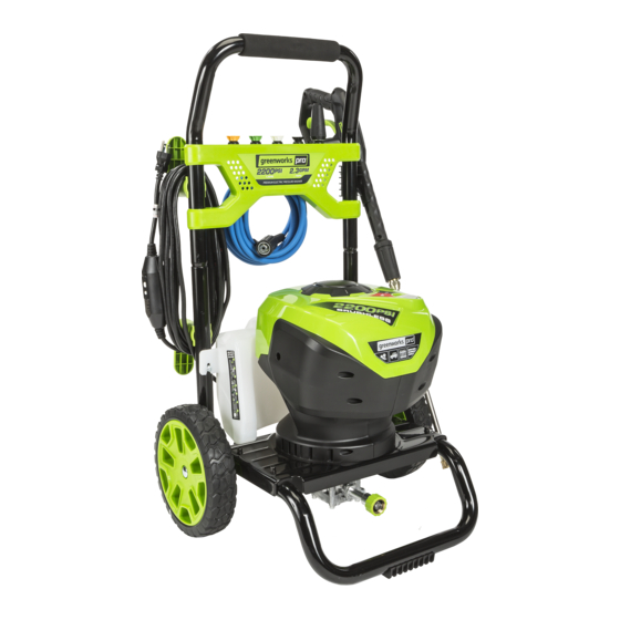
Summary of Contents for GreenWorks Pro GPW 2200
- Page 1 2200 PSI / 1.2 GPM ELECTRIC PRESSURE WASHER GPW 2200 OPERATOR’S MANUAL TOLL-FREE HELPLINE: 1-855-345-3934 Read all safety rules and instructions carefully before operating this tool. www.greenworkstools.com...
-
Page 2: Table Of Contents
INSTRUCTION Important Safety Instructions………………………………………………………........3 Specific Safety Rules……………………………………………………………….........5 Symbols……………………………………………………………………………….........7 Electrical………………………………………………………………………………........9 Know Your Pressure Washer…………………………………………………………........10 Packing List..............................11 Assembly………………………………………………………………………………........12 Operation………………………………………………………………………………........17 Maintenance…………………………………………………………………………........22 Troubleshooting………………………………………………………………………........25 Warranty…………………………………………………………………………………….......28 Exploded View…………………………………………………………………………........….29 Parts List………………………………………………………………………………........30 PRODUCT SPECIFICATION Induction Motor………………………………………………………........Brushless motor Power Cord with In-Line GFCI........................35ft Max. Pounds Per Square Inch Pressure……………………………………........2200psi Rated Gallons Per Minute…………………………………………..………........1.2 GPM Max Gallons Per Minute at 100PSI……………………………………..………......2.3 GPM Maximum Inlet Water Temperature……………………………………………..……....104°F(40℃)... -
Page 3: Important Safety Instructions
IMPORTANT SAFETY INSTRUCTIONS W A R N I N G Read and understand all instructions. Failure to follow all instructions listed below may result. in electric shock, fire, and/or serious personal injury. W A R N I N G When using this product, basic precautions should always be followed. READ ALL INSTRUCTIONS BEFORE USING THIS PRODUCT ■... - Page 4 IMPORTANT SAFETY INSTRUCTIONS EXTENSION CORDS When using a power tool at a considerable distance from a power source, be sure to use an extension cord that has the capacity to handle the current the product will draw. An undersized cord will cause a drop in line voltage, possibly resulting in overheating, loss of power, and/or circuit breaker or GFCI tripping.
-
Page 5: Specific Safety Rules
SPECIFIC SAFETY RULES ■ Know your product. Read the operator’s manual carefully. Learn the machine’s applications and limitations as well as the specific potential hazards related to this product. ■ To reduce the risk of injury, keep children and visitors away. All visitors should keep a safe distance from the work area. - Page 6 SPECIFIC SAFETY RULES W A R N I N G High pressure jets can be dangerous if subject to misuse. The jet must not be directed at people, animals, electrical devices, or the machine itself. ■ Keep the motor away from flammables and other hazardous materials. ■...
-
Page 7: Symbols
SYMBOLS Some of the following symbols may be used on this product. Please study them and learn their meaning. Proper interpretation of these symbols will allow you to operate the product better and safer. DESIGNATION/EXPLANATION SYMBOL NAME Volts Voltage Amperes Current Frequency (cycles per second) Hertz... - Page 8 SYMBOLS The following signal words and meanings are intended to explain the levels of risk associated with this product. SYMBOL SIGNAL MEANING Indicates an imminently hazardous situation, which, if not avoided, will result in death or serious injury. DANGER Indicates a potentially hazardous situation, which, if not avoided, could result in death or serious injury.
-
Page 9: Electrical
ELECTRICAL ELECTRICAL CONNECTION This product has a precision-built brushless motor. It should be connected to a power supply that is 120 volts, 60 Hz, AC only (normal household current). Do not operate this product on direct current (DC). A substantial voltage drop will cause a loss of power and the motor will overheat. If the product does not operate when plugged into an outlet, double check the power supply. -
Page 10: Know Your Pressure Washer
KNOW YOUR PRESSURE WASHER The safe use of this product requires an understanding of the information on the tool and in this operator’s manual as well as a knowledge of the project you are attempting. Before use of this product, familiarize yourself with all operating features and safety rules. -
Page 11: Packing List
PACKING LIST PART NAME ERP NO. FIGURE PART NO. • Pressure Washer • Upper Handle Assembly 311201936 (including the spray tips) • Front panel assembly 341001936 (spray tip included) • Sprayer gun (trigger) 31140636-1 • Wand assy 31145363 • Gun Holder 341101936 •... -
Page 12: Assembly
ASSEMBLY UNPACKING This product requires assembly. ■ Carefully remove the product and any accessories from the box. Make sure that all items listed in the packing list are included. W A R N I N G Do not use this product if any parts on the Packing List are already assembled to your product when you unpack it. - Page 13 ASSEMBLY ASSEMBLING THE WHEEL (See Figure 3.) ■ Insert the axle through the wheel and through the frame. ■ Slide the washer over the axle pass the pin hole. ■ Insert the pin through the hole to firmly fasten the wheel. Wheels Washer Fig.
- Page 14 ASSEMBLY ASSEMBLING THE FRONT PANEL AND GUN HOLDER (See Figure 5.) ■ Line up the screw sleeves with the holes in the upper handle and push through. ■ Insert the screw and turn clockwise with a phillips head screw driver (not included) until the screw is tight.
- Page 15 ASSEMBLY ASSEMBLING THE HIGH PRESSURE HOSE ■ Connect one end of the hose to the water outlet connector, while the other end to the trigger gun. (See Figure 6.) ① ② High Pressure Outlet Hose Connector Fig. 6-1 Fig. 6-2 CONNECTING HIGH PRESSURE HOSE TO TRIGGER HANDLE (See Figure 6-2.) 1.
- Page 16 ASSEMBLY CONNECTING THE GARDEN HOSE (See Figure 8.) C A U T I O N : Always observe all local regulations when connecting hoses to the water main. Some areas have restrictions against connecting directly to public drinking water supply to prevent the feedback of chemicals into the drinking water supply.
-
Page 17: Operation
OPERATION W A R N I N G Do not allow familiarity with the product to make you careless. Remember that a careless fraction of a second is sufficient to inflict serious injury. W A R N I N G Always wear eye protection with side shields marked to comply with ANSI Z87.1. - Page 18 OPERATION ■ Remove cap from detergent tank ■ Pour detergent into tank ■ Reinstall cap Use Black Soap Tip Only Detergent Tank Fig. 9-1 Fig. 9-2 C A U T I O N : Use only approved pressure washer cleaners. Do not use bleach, chlorine,or any cleaners containing acids.
- Page 19 OPERATION STARTING AND STOPPING THE PRESSURE WASHER (See Figure 10.) C A U T I O N : Do not run the pump without the water supply connected and turned on. ■ Connect the garden hose. ■ Turn the garden hose on then squeeze the trigger and run water hose with motor in OFF position until a steady stream of water appears.
- Page 20 OPERATION USING THE SPRAY TIPS (See Figure 11.) Each of the spray tips has a different spray pattern. Before starting any cleaning job, determine the best spray tip for the job. The following chart offers some general guidelines to help you choose the best spray tip for your application.
- Page 21 OPERATION Black - Soap spray tip ■ The black soap spray tip, is used for soap application. Soap is applied under low pressure high volume for optimum performance. Soap cannot be applied under SOAP high pressure with this machine. Turbo Nozzle Tip ■...
-
Page 22: Maintenance
MAINTENANCE OPERATING THE PRESSURE WASHER (See Figure 13.) Use only detergents designed for pressure washers. Many detergents may requrie mixing prior to use. Prepare cleaning solution as instructed on the solution bottle. Fig. 13 To clean: ■ Pour detergent in the detergent tank. ■... - Page 23 MAINTENANCE W A R N I N G When servicing, use only identical replacement parts. Use of any other parts may create a hazard or cause product damage. W A R N I N G Before inspecting, cleaning or servicing the machine, turn off the unit, unplug from the outlet, pull trigger to release water pressure and disconnect the high pressure hose.
- Page 24 MAINTENANCE Using the spray tip cleaning tool provided, free any foreign materials clogging or restricting the spray tip opening. Refer to Fig. 14 ■ Using a garden hose, flush debris out of the spray tip by back flushing (running the water through the spray tip backwards or from the outside to the inside).
-
Page 25: Troubleshooting
TROUBLESHOOTING PROBLEM POSSIBLE CAUSE SOLUTION On/Off switch is in the Turn switch to the “ON” ( | ) position. “OFF” (O) position. Power cord is not Plug in power cord. plugged in. Electrical outlet does not supply adequate Try a different outlet. power. - Page 26 TROUBLESHOOTING PROBLEM POSSIBLE CAUSE SOLUTION Detergent is too thick. Dilute detergent. Filter on detergent Run warm water through filter to remove build- suction tube is clogged. Detergent is not coming Damaged or clogged Remove obstruction or replace detergent out. detergent suction suction tube.
- Page 27 TROUBLESHOOTING PROBLEM POSSIBLE CAUSE SOLUTION Supply voltage below Verify that only the pressure washer is running minimum. on this circuit. System has residual Turn unit “OFF”, squeeze trigger on spray wand to release pressure, then turn unit "ON". pressure. Voltage loss due to Unplug any extension cords attached and plug Motor buzzes but fails to extension cord.
-
Page 28: Warranty
WARRANTY GREENWORKS™ hereby warranties this product, to the original purchaser with proof of purchase, for a period of one (1) years against defects in materials, parts or workmanship. GREENWORKS™, at its own discretion will repair or replace any and all parts found to be defective, through normal use, free of charge to the customer. -
Page 29: Exploded View
EXPLODED VIEW EN - 29... -
Page 30: Parts List
PARTS LIST ITEM NO. PART NO. DESCRIPTION 311201936 Upper handle assy 349011936 Foam 331031936 Upper handle 322021822 Screw 33306847 Spring bnutton 322011628 Screw 341101936 Gun holder 322011635 Screw 311211936 Cord retainer 341071833 Connector 341101635 Cord retainer 32913847 Washer 322021635 Screw 333011936 Hose holder 341001936... - Page 31 PARTS LIST 32222301A 322021822 Screw 341201936 Bracket support 341041936 Decorative cover 311311936 Decorative cover assy 24.1 341071936 Decorative cover 24.2 341151936 Transparent indicator panel 32208302A Screw 341081936 Left housing 331011836 AC brushless activator 341091936 Left housing 322031635 Screw 322011936 Screw 311501936 PCB LED indicator 311221936...
- Page 32 PARTS LIST Switch box cover 341181936 341071923 Hose connector 34202368 O-ring 332031936 Water outlt connector 34125304 Dust cap 31140363-1 GW gun assy 31145363 GW gun wand assy 311311635 High pressure hose 33201671 Tip cleaner TOLL-FREE HELPLINE: 1-855-345-3934 Rev: 00 (12-11-16) EN - 32...
Need help?
Do you have a question about the GPW 2200 and is the answer not in the manual?
Questions and answers