CIB UNIGAS C120A Manual Of Installation - Use - Maintenance
Gas-light oil burners
Hide thumbs
Also See for C120A:
- Manual of installation - use - maintenance (128 pages) ,
- Manual of installation - use - maintenance (228 pages)

Related Manuals for CIB UNIGAS C120A


Summary of Contents for CIB UNIGAS C120A
- Page 1 C92A C120A Progressive - Fully Modulating Double stage Gas - Light oil burners MANUAL OF INSTALLATION - USE - MAINTENANCE BURNERS - BRUCIATORI - BRULERS - BRENNER - QUEMADORES - ГОРЕЛКИ M039450CA 0.5 07/2023...
-
Page 2: Risk Analysis
DANGERS, WARNINGS AND NOTES OF CAUTION - Faults in the fuel supply system; - Use of the burner even after an error and/or fault has occurred; - Repairs and/or overhauls incorrectly carried out; This manual is supplied as an integral and essential part of - Modification of the combustion chamber with inserts that prevent the the product and must be delivered to the user. - Page 3 GENERAL INSTRUCTIONS DEPENDING ON FUEL USED those parts likely to constitute sources of danger shall be made harm- less. ELECTRICAL CONNECTION In case the equipment is to be sold or transferred to another user, or in For safety reasons the unit must be efficiently earthed and installed as ...
-
Page 4: Symbols Used
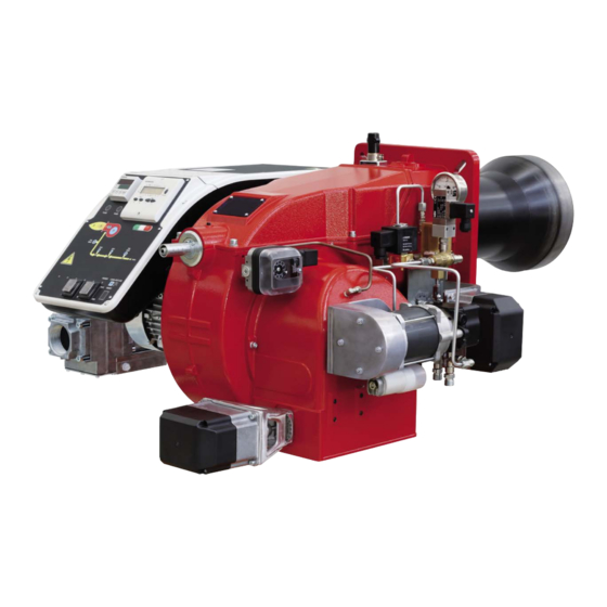
BURER DATA PLATE .Do not touch any mechanical moving parts with your hands Consump or any other part of your body. Injury hazard Do not touch any parts containing fuel (i.e. tank and pipes). Type For the following information, please refer to Scalding hazard Model the data plate:... - Page 5 PART I: SPECIFICATIONS PART I: SPECIFICATIONS BURNERS FEATURES Note: the figure is indicative only Mimic panel with startup switch Gas valves groupElectrical panel Electrical panel Cover Blast tube + Combustion head Flange Oil pressure governor Pump Air intakeSilencer 10 Air pressure switch 11 Adjusting cams 12 Actuator 13 Head adjusting ring nut...
-
Page 6: Burner Type
Burners are identified by burner type and model. Burner model identification is described as follows. Type C92A Model MG-. PR. SP. BURNER TYPE C92A, C120A M - Natural gas B - Biogas FUEL L - LPG G - Light oil... -
Page 7: Technical Specifications
PART I: SPECIFICATIONS Technical Specifications BURNER TYPE C92A MG.. C120A MG.. C92A MG.. C120A MG.. 250 - 920 300 - 1200 250 - 920 300 - 1200 Output min. - max. kW MG - Natural gas-Light oil LG - LPG-Light oil... - Page 8 Overall dimensions (mm) C92A PR/MD.. Burner with aluminium air inlet 1008 1192 Boiler recommended drilling tem- Burner flange plate...
- Page 9 Overall dimensions (mm) C120A PR/MD..Burner with aluminium air inlet 1335 1008 Boiler recommended drilling Burner flange template Boiler recommended drilling Counterflange OPTIONAL template...
- Page 10 (< 1200kW) ( max output > 1200kW) Fig. 4 - 3I2MG-09 v1 Hydraulic diagram ON BOARD ITEMS SUPPLIED LOOSE ITEMS LEGEND OIL TRAIN Filter Flexible hose Pump and pressure governor oil inlet Electrical motor Flexible hose oil outlet Solenoid valve Solenoid valve Flexible hose Oil distributor...
- Page 11 PART I: SPECIFICATIONS GAS TRAIN CONNECTION ATTENTION: Before executing the connections to the gas pipe network, be sure that the manual cutoff valves are closed. The following diagrams show some examples of possible gas trains with the components supplied with the burner and those fitted by the installer.
-
Page 12: Performance Curves
Pressure in the Network / gas flow rate curves C92A MG.. C120A MG.. ATTENTION: the gas rate value is quoted on the x-axis, the related network pressure is quoted on the y-axis (pressure value in the combustion chamber is not included). To know the minimum pressure at the gas train inlet, necessary to get the requested gas rate, add the pressure value in the combustion chamber to the value read on the y-axis. - Page 13 PART I: SPECIFICATIONS Pressure - rate in combustion head curves Curves are referred to pressure = 0mbar in the combustion chamber! C92A M-.. C120A M-..
- Page 14 PART I: SPECIFICATIONS How to read the burner “Performance curve” To check if the burner is suitable for the boiler to which it must be install- Campo di lavoro bruciatori led, the following parameters are needed: Tipo P60 Mod. M-xx.x.IT.A.0.50 - M-.xx.x.IT.A.0.65 furnace input, in kW or kcal/h (kW = kcal/h/860);...
- Page 15 Packing The burners are despatched in wooden crates whose dimensions are: C92A-C120A: 1330 mm x 820 mm x 600 mm (L x P x H) Such packages fear moisture and are not suitable for stacking.Packing cases of this type are affected by humidity and are not suitable for stacking.
- Page 16 PART II: INSTALLATION Fitting the burner to the boiler To install the burner into the boiler, proceed as follows: make a hole on the closing door of the combustion chamber as described on paragraph “Overall dimensions”) place the burner to the boiler: lift it up and handle it according to the procedure described on paragraph “Handling the burner”; place the 4 stud bolts (5) on boiler’s door, according to the burner drilling template described on paragraph “Overall dimensions”;...
- Page 17 PART II: INSTALLATION GAS TRAIN CONNECTIONS WARNING: before executing the connections to the gas pipe network, be sure that the manual cutoff valves are closed. ATTENTION: it is recommended to mount filter and gas valves to avoid that extraneous material drops inside the valves, during maintenance and cleaning operation of the filters (both the filters outside the valves group and the ones built-in the gas valves).
-
Page 18: Mounting Positions
PART II: INSTALLATION MultiBloc MB-DLE - Assembling the gas train Mounting Mount flange onto tube lines: use appropriate sealing agent Insert MB-DLE: note position of O rings Remove MultiBloc between the threaded flanges After installation, perform leakage and functional test Disassembly in reverse order MB-DLE 405.. - Page 19 PART II: INSTALLATION DUNGS MBE Components and position of pressure switches PGMIN minimum gas pressure switch VD-V VD-R PGMIN minimum gas pressure switch (alternative VD-V VD-R to 1) PGCP leakage control gas pressure switch PGMAX maximum gas pressure switch Actuator with integrated pressure stabiliser On-Off actuator Valve body (Threaded) Valve body (Flange)
- Page 20 PART II: INSTALLATION Siemens VGD20.. e VGD40.. Components and position of pressure switches PGMIN minimum gas pressure switch SKP25 SKP25 PGMIN minimum gas pressure switch (alternative SKP15 SKP15 to 1) PGCP leakage control gas pressure switch PGMAX maximum gas pressure switch Actuator with integrated pressure stabiliser On-Off actuator Valve body (Threaded)
- Page 21 PART II: INSTALLATION Siemens VGD Pressure taps Strainer (G 1/4") (G 1/8") (G 1/4") (G 1/8") (G 1/4") (G 3/4") (G 1/8") Legend pi Inlet pressure pm Pressure between valves po Outlet pressure Integrated proving system (burners equipped with LME7x, LMV, LDU) This paragraph describes the integrated proving system operation sequence: At the beginning both the valves (EV1 and EV2) must be closed.
- Page 22 PART II: INSTALLATION OIL TRAIN CONNECTIONS Hydraulic diagrams for light oil supplying circuits GRAVITY CIRCUIT RING CIRCUIT 1 Manual valve 2 Light oil filter 3 Light oil feeding pump 4 One way valve 5 Flexible hoses 6 Relief valve SUCTION CIRCUIT NOTE: in plants where gravity or ring feed systems are provided, install an automatic interception device.
- Page 23 PART II: INSTALLATION eding. If provided, the inside by-pass plug must be installed to avoid air and fuel passing through the pump. Burners come out from the factory provided for double-pipe systems. They can be suited for single-pipe system (recommended in the case of gravity feed) as decribed before.To change from a 1-pipe system to a 2-pipe-system, insert the by-pass plug G (as for ccw-rota- tion- referring to the pump shaft).
- Page 24 PART II: INSTALLATION Suntec TA.. Oil viscosity 3 ÷ 75 cSt Oil temperature 0 ÷ 150°C 1. Inlet G1/2 Min. suction pressure - 0.45 bar to avoid gasing 2. To the nozzle G1/2 Max. suction pressure 5 bar 3. Return G1/2 Max.
-
Page 25: Electrical Connections
PART II: INSTALLATION ELECTRICAL CONNECTIONS WARNING! Respect the basic safety rules. make sure of the connection to the earthing system. do not reverse the phase and neutral connections. fit a differential thermal magnet switch adequate for connection to the mains. WARNING! before executing the electrical connections, pay attention to turn the plant’s switch to OFF and be sure that the burner’s main switch is in 0 position (OFF) too. - Page 26 PART III: OPERATION PART III: OPERATION DANGER! Incorrect motor rotation can seriously damage property and injure people. DANGER: During commissioning operations, do not let the burner operate with insufficient air flow (danger of formation of carbon monoxide); if this should happen, make the gas decrease slowly until the normal combustion values are achieved. WARNING: before starting the burner up, be sure that the manual cutoff valves are open and check that the pressure upstream the gas train complies the value quoted on paragraph “Technical specifications”.
-
Page 27: Fuel Selection
PART III: OPERATION Double-stage burners Keys Main switch (0=Off, 1=GAS, 2=OIL) Lock-out LED Hi-flame operation LED Lo-flame operation LED “Ignition transformer operation” LED “Fan motor overload tripped” LED Gas valves EV2 operation signalling lamp Gas valves EV1 operation signalling lamp Gas pressure switch signal lamp Gas proving system lockout signalling lamp EVG1 solenoid valve operation LED... -
Page 28: Light Oil Operation
PART III: OPERATION The burner is now operating, meanwhile the actuator goes to the high flame position and, after some seconds, the two-stage ope- ration begins; the burner is driven automatically to high flame or low flame, according to the plant requirements. Operation in high or low flame is signalled by lamp B2 on the frontal panel. - Page 29 PART III: OPERATION FLUIDICS KW3...45° NOZZLE SUPPLY PRESSURE = 20 bar. VISCOSITY AT NOZZLE = 5 cSt The nominal size of the nozzle is indicated at the ends of the curve Pressure on return (bar) The nominal size of the nozzle is indicated at the ends of the curve Pressure on return (bar) The nominal size of the nozzle is indicated at the ends of the curve Pressure on return (bar)
- Page 30 PART III: OPERATION FLUIDICS KW3...45° NOZZLE SUPPLY PRESSURE = 20 bar. VISCOSITY AT NOZZLE = 5 cSt The nominal size of the nozzle is indicated at the ends of the curve Pressure on return (bar) The nominal size of the nozzle is indicated at the ends of the curve Pressure on return (bar) The nominal size of the nozzle is indicated at the ends of the curve Pressure on return (bar)
- Page 31 PART III: OPERATION FLUIDICS KW3...45° NOZZLE SUPPLY PRESSURE = 20 bar. VISCOSITY AT NOZZLE = 5 cSt The nominal size of the nozzle is indicated at the ends of the curve Pressure on return (bar) The nominal size of the nozzle is indicated at the ends of the curve Pressure on return (bar) The nominal size of the nozzle is indicated at the ends of the curve Pressure on return (bar)
- Page 32 PART III: OPERATION FLUIDICS KW3...60° NOZZLE SUPPLY PRESSURE = 20 bar. VISCOSITY AT NOZZLE = 5 cSt The nominal size of the nozzle is indicated at the ends of the curve Pressure on return (bar)
- Page 33 PART III: OPERATION FLUIDICS KW3...60° NOZZLE SUPPLY PRESSURE = 20 bar. VISCOSITY AT NOZZLE = 5 cS The nominal size of the nozzle is indicated at the ends of the curve Pressure on return (bar) The nominal size of the nozzle is indicated at the ends of the curve Pressure on return (bar)
- Page 34 PART III: OPERATION FLUIDICS KW3...60° NOZZLE SUPPLY PRESSURE = 20 bar. VISCOSITY AT NOZZLE = 5 cSt The nominal size of the nozzle is indicated at the ends of the curve Pressure on return (bar) The nominal size of the nozzle is indicated at the ends of the curve Pressure on return (bar) The nominal size of the nozzle is indicated at the ends of the...
- Page 35 PART III: OPERATION Air and Gas Flow Rate Settings by means of Berger STM30../Siemens SQM40.. actuator check the fan motor rotation. Only for burners provided with Multibloc MB-DLE gas valves: before starting the burner up, set the slow opening. To set the slow opening, remove cover T, reverse it upside down and use it as a tool to rotate screw VR.
-
Page 36: Adjustments For Gas Operation
PART III: OPERATION Gas throttle valve open Gas throttle valve closed 18 Move again the gas low flame microswitch towards the minimum to meet the next screw on the adjusting cam and repeat the pre- vious step; go on this way as to reach the desired low flame point. 19 Now adjust the pressure switches. - Page 37 PART III: OPERATION Only for burners provided with Dungs Multibloc MB-DLE gas valves:before starting the burner up, adjust the valves slow opening. To set the fast opening remove cover T, reverse it upside down and use it as a tool to rotate screw VR. Clockwise rotation reduces start flow rate, anticlockwise rotation increases it.
- Page 38 PART III: OPERATION 10 In the case that the flue gas temperature is not the one required, go back to the light oil operation and adjust the oil flow rate as to meet the flue gas temperature values reqested. Consequently adjust the air always observing the combustion analysis. Then go back to the gas operation and repeat only the gas adjustments (because the air rate has already been set in the light oil operation);...
- Page 39 PART III: OPERATION Progressive burners Once the air and gas flow rates are adjusted, turn the burner off, switch to the oil operation (OIL, on the burner control panel). with the electrical panel open, prime the oil pump acting directly on the related CP contactor (see next picture): check the pump motor rotation and keep pressing for some seconds until the oil circuit is charged;...
- Page 40 PART III: OPERATION motor rotation and keep pressing for some seconds until the oil circuit is charged; bleed the air from the M pressure gauge port by loosing the cap without removing it, then release the contactor. Suntec E7 Suntec TA. Suntec AJ6 drive the burner to high flame stage, by means fo the thermostat TAB (high/low flame thermostat - see Wiring diagrams).
- Page 41 PART III: OPERATION D Adjusting screw cap Pressure adjusting screw M Pressure gauge port VT Needle screw B Return to tank CReturn from nozzle Fig. 10 always checking the combustion values, adjust the low flame air flow rate by means of the actuator ST1 (Berger)/III (Siemens) cam;...
- Page 42 PART III: OPERATION Remove the transparent plastic cap. While the burner is operating at the maximum output, test the gas pressure on the pressure port of the minimum gas pressure switch. Slowly close the manual cutoff valve (placed upstream the pressure switch, see gas train installation diagram), until the detected ...
- Page 43 PART III: OPERATION Center head holes gas flow regulation for C120A burner with LPG To adjust the gas flow, partially close the holes, as follows: loosen the three V screws that fix the adjusting plate D; insert a screwdriver on the adjusting plate notches and let it move CW/CCW as to open/close the holes;...
- Page 44 PART IV: MAINTENANCE PART IV: MAINTENANCE At least once a year carry out the maintenance operations listed below. In the case of seasonal servicing, it is recommended to carry out the maintenance at the end of each heating season; in the case of continuous operation the maintenance is carried out every 6 months.
- Page 45 PART IV: MAINTENANCE MultiBloc MBE MultiBloc VD Mounting to push position 1. Position VD on VB, fig. 2+3. 2. Slide VD forward up to the stop, fig. 4. 3. Screw VD on with 2 M5 screws for each, max. 5 Nm/44 in.-lb., fig. 5/6. 4.
-
Page 46: Electrodes Adjustment
Important Note: Check the ignition and detection electrodes after removing/adjusting the combustion head. ATTENTION: avoid the ignition and detection electrodes to contact metallic parts (blast tube, head, etc.), otherwise the boiler’s operation would be compromised. Check the electrodes position after any intervention on the combustion head. C92A, C120A 24.1 Cleaning/replacing the electrodes ATTENTION: avoid the electrodes to get in touch with metallic parts (blast tube, head, etc.), otherwise the boiler... -
Page 47: Seasonal Stop
PART IV: MAINTENANCE Checking the detection current To check the detection signal follow the scheme in the picture below. If the signal is less than the value indicated, check the position of the detection electrode or detector, the electrical contacts and, if necessary, replace the electrode or the detector. Control box Minimum detection signal 70µA (with UV detector) - Page 48 PART IV: MAINTENANCE TROUBLESHOOTING GUIDE Gas operation * No electric power supply * Restore power supply * Main switch open * Close switch * Thermostats open * Check set points and thermostat connections * Bad thermostat set point or broken thermostat * Reset or replace the thermostat * No gas pressure * Restore gas pressure...
- Page 49 PART IV: MAINTENANCE TROUBLESHOOTNG GUIDE Light oil operation * No electric power supply * Wait for electric power supply is back * Main switch open * Close the switch * Thermostats open * Check set points and thermostat connections * Bad thermostat set point or broken thermostat * Set or replace the thermostat * No gas pressure * Restore gas pressure...
- Page 52 C.I.B.UNIGAS S.p.A. Via L.Galvani ,9 - 35011Campodarsego (PD) - ITALY Tel. +39 049 9200944 - Fax +39 049 9200945 website:www.cibunigas.it-e-mail:cibunigas@cibunigas.it Le informazioni contenute in questo documento sono puramente indicative e non impegnative. L’azienda si riserva la facoltà di apportare modifiche senza obbligo di preavviso.
- Page 53 LME73.000Ax + PME73.831AxBC LME73.831AxBC Service instruction manual M12921CB Rel.1.2 02/2016...
-
Page 54: General Features
GENERAL FEATURES LME/ is suitable for gas, light and heavy oil burners LME7 series has two devices: LME73.000 (hardware) and PME73.831AxBC (programmable unit). The LME73.831AxBC is also available: it has a built in software and it isa not programmable. LME7 is inside the control panel. If supplied, PME73.831BC is inside the LME7; The display AZL23.. -
Page 55: User Interface
User interface : Button A - Display preset output - In lockout position: Power value to the time of fault Info and Enter button - Reset in the event of fault, changeover visual diagnostic of the cause of fault (refer to chapter Diagnostics of cause of fault ) - button - Display flame signal current 2 or phases display - In lockout position: MMI phase to the time of fault... - Page 56 List of phase display on board LME : Phase number of Function 7-segment display Standby Standby, waiting for heat demand Mains ON / test phase (e.g. detector test) Startup Yellow Safety valve ON, air pressure switch test / POC test (timeout / locking Yellow Fan motor ON / air pressure switch test / settling time Yellow...
- Page 57 Operation : The lockout reset button (info button) (EK) is the key operating element for resetting the burner control and for activating / deactivating the diagnostics functions. The multicolor signal lamp (LED) is the key indicating element for visual diagnostics. Both lockout reset button (EK) and signal lamp (LED) are located in the control panel.
-
Page 58: Program Sequence
Program sequence : Version 1: • Ignition load < low-fire • Prepurging in high-fire • Parameter 515 = 1 (condition parameter 259.01 > 0 seconds) - Page 59 Program sequence : Version 2: • Ignition load > low-fire • Prepurging in high-fire • Parameter 515 = 1 (condition parameter 259.01 = 0 seconds)
- Page 60 Phase Function number Lockout phase Standby, waiting for heat demand Operation, modulating operation Interval until release of load controller target (analog or 3-position step input) Under voltage Safety loop open Extraneous light on burner startup (timeout/locking after 30 seconds) Mains ON/test phase (e.g. detector test) Shutdown, actuator opens in CLOSE position (homerun) Safety valve ON, air pressure switch OFF, actuator opens in CLOSE position Part 1: Fan motor ON...
- Page 61 Error code table : Red blink code of fault signal lamp (LED) Possible cause 2 x blinks No establishment of flame at the end of the safety time (TSA) - Faulty or soiled flame detector - Faulty or soiled fuel valves - Poor adjustment of burner, no fuel - Faulty ignition equipment 3 x blinks...
- Page 62 Flame detection – detection electrode : Short-circuit current Max. AC 1 mA Required detector current Min. DC 2 μA, display approx. 45 % Possible detector current Max. DC 3 μA, display approx. 100 % Permissible length of detector cable (laid separately) 30 m (core-earth 100 pF/m) Measuring circuit Keys...
- Page 63 Gas proving system : Valve proving is dependent on input valve proving ON / OFF (X2-02). When a leak is detected, the gas valve proving function ensures that the gas valves will not be opened and that ignition will not be switched on. Lockout will be initiated. Valve proving with separate pressure switch (P LT) Step 1: td4 –...
- Page 64 Instruction, control and modify via AZL2x : The AZL2x.. display/programming unit is shown below: The keys functions are the following: Key F + A While pressing the two keys contemporarly, the code message will appear: by entering the proper password it is possible to access the Service mode. Info and Enter keys Used for Info and Service menues Used as Enter key in the setting modes...
- Page 65 The display will show these data: Lock+unlock codes Flame Open valves Ignition transformers energised Fan motor energised Oil pre-heater energised Plant heat request Parameter setting mode Info mode Service mode Closing actuator Opening actuator Unit measure While pushing the button together with whatever else button, LME73 locks out; the display shows On stand-by position, appears On operation, all the phases appears with their number.
- Page 66 List of phase with display AZL2x : Phase number Function Standby Standby, waiting for heat request Ph08 Power ON / test phase (e.g. detector test) Startup Ph21 Safety valve ON, air pressure switch test / POC test (timeout / locking after 5 seconds), actuator opens in low-fire position / CLOSE position Ph22 Fan motor ON or air pressure switch test / settling time...
- Page 67 Error code list with operation via internal AZL : Error code Clear text Possible cause Loc 2 No establishment of flame at the - Faulty or soiled fuel valves end of the safety time (TSA) - Faulty or soiled flame detector - Poor adjustment of burner, no fuel - Faulty ignition equipment Loc 3...
- Page 68 Entering the Parameter levels: y means of a proper use of the keys, it is possible to enter the various level parameters, as shown in the following flow chart :...
- Page 69 Info level : Keep pushing the button until appears. Use + or - for scrolling the parameter list. If on the right side a dash-dot appears, it means the display doesn't show the full description. Push again for 1 to 3 s in order to show the full description. Below the visible Info parameters: Parameter Parameter list...
- Page 70 Service level : Keep pushing the button until appears. Use + or - for scrolling the parameter list. . If on the right side a dash-dot appears, it means the display doesn't show the full description. Push again for 1 to 3 s in order to show the full description. Below the visible Info parameters: Parameter Parameter list...
- Page 71 Process data Normalized speed Read only 100% 0.01 % Service Mains voltage Read only LME73.000A1: Service 175 V LME73.000A2: 350 V Flame intensity Read only 100% Service...
- Page 72 Parameter level (Heating engeneering) : This level lets the engineer to modify some burner parameters. It is protect with a 4 digit password (SO level) and a 5 digit password (OEM level) Password input : push F and A buttons together until the display shows "code" and 7 underlines. The left one flashes. By move the flashing underline until it is on the desired position and push "enter".
- Page 73 Repetition in the event of loss of flame during operation Edit 0 SO 0 = None 1 = None 2 = 1 x Repetition 241.00 Valve proving Edit 1 SO 0 = Off 1 = On 241.01 Valve proving Edit 0 SO 0 = During prepurge time (t1) 1 = During postpurge time (t8)
- Page 74 Power setting Analog input (feedback potentiometer ASZxx.3x required) Edit 0 SO 0 = 3-position step input 1 = 0...10 V 2 = 0...135 Ω 3 = 0...20 mA 4 = 4...20 mA with lockout at I <4 mA 5 = 4...20 mA WARNING Parameter Num.
- Page 76 Note: Specifications and data subject to change. Errors and omissions excepted.
- Page 77 QF-A QF-B...
- Page 80 LPGMIN...
- Page 81 LEVG LEV1 LEV2 SOLO CON CONTROLLO TENUTA WITH GAS LEAKAGE TEST ONLY...
- Page 85 QF-A QF-B...
Need help?
Do you have a question about the C120A and is the answer not in the manual?
Questions and answers