
Related Manuals for CIB UNIGAS TN 1030


Summary of Contents for CIB UNIGAS TN 1030
- Page 1 TN1030 TN1050 Heavy oil Industrial Burners MANUAL OF INSTALLATION - USE - MAINTENANCE BURNERS - BRUCIATORI - BRULERS - BRENNER - QUEMADORES - ГОРЕЛКИ M039208CA REV. 0 03/2008...
-
Page 3: General Introduction
WARNINGS THIS MANUAL IS SUPPLIED AS AN INTEGRAL AND ESSENTIAL PART OF THE PRODUCT AND MUST BE DELIVERED TO THE USER. INFORMATION INCLUDED IN THIS SECTION ARE DEDICATED BOTH TO THE USER AND TO PERSONNEL FOLLOWING PRO- DUCT INSTALLATION AND MAINTENANCE. THE USER WILL FIND FURTHER INFORMATION ABOUT OPERATING AND USE RESTRICTIONS, IN THE SECOND SECTION OF THIS MANUAL. -
Page 4: Directives And Standards
the power-driven components in the system (i.e. pumps, burner, etc.) DIRECTIVES AND STANDARDS should be switched off. Gas burners European directives: 3b) FIRING WITH GAS, LIGHT OIL OR OTHER FUELS - Directive 90/396/CEE - Gas Appliances; Directive 2006/95/EC on low voltage;... -
Page 5: General Features
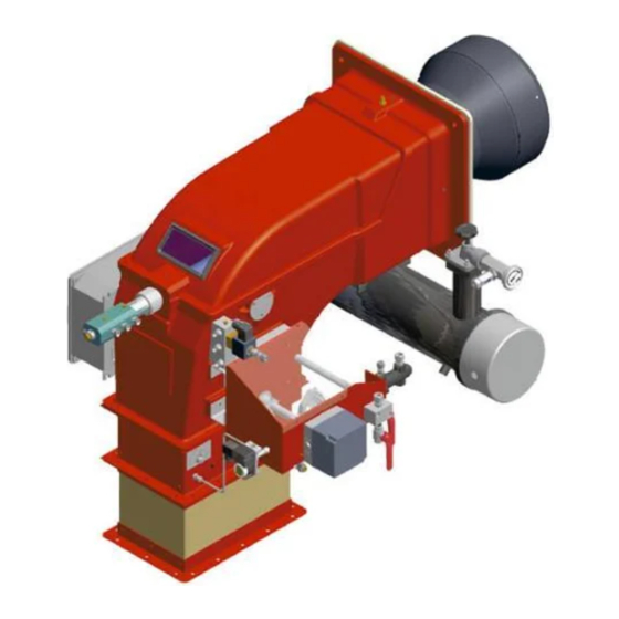
CIB UNIGAS - M039208CA PART I: INSTALLATION MANUAL GENERAL FEATURES This series of industrial burners is designed for all those applications that require big-sized air fans or air-flue heat exchangers to be installed in sound-proof areas to reduce noise. They can be provided with built-in or separately-mounted control panel (console or wall- mounted. -
Page 6: Burner Model Identification
CIB UNIGAS - M039208CA backpressure (data are available on the boiler ID plate or in the user’s manual). Burners provided with built-in control panel are designed for IP40 index of protection. For other values of IP, please contact the CIB UNIGAS Technical Dpt. -
Page 7: Specifications
CIB UNIGAS - M039208CA Specifications Note: Output values are valid for comburent air temperature lower than 50°C. TN 1030 TN 1050 Output 2550 - 13000 3500 - 15500 Fuel Heavy oil °E, 50 °C Oil viscosity Flow rate kg/h 227 - 1158... - Page 8 Overall dimensions (mm) (TN1030) Boiler drilling plate and burner flange Air inlet flange...
-
Page 9: Installing The Fan
CIB UNIGAS - M039208CA MOUNTING AND CONNECTING THE BURNER Packing The burners are despatched in wooden crates whose dimensions are: 2280 x 1730 x 1360mm (L x P x H) Packing cases of this kind are affected by humidity and are not suitable for stacking. In each packing case, you will find: burner;... -
Page 10: Burner Ignitor
CIB UNIGAS - M039208CA Matching the burner to the boiler The burners described in this manual have been tested with combustion chambers that comply with EN676 regulation and whose dimensions are described in the diagram . In case the burner must be coupled with boilers with a combustion chamber smaller in dia- meter or shorter than those described in the diagram, please contact the supplier, to verify that a correct matching is possible, with res- pect of the application involved. -
Page 11: Hydraulic System
CIB UNIGAS - M039208CA Hydraulic system The pumps that are used can be installed both into single-pipe and double-pipe systems. Single-pipe system: a single pipe drives the oil from the tank to the pump’s inlet. Then, from the pump, the pressurised oil is driven to the nozzle: a part comes out from the nozzle while the othe part goes back to the pump. - Page 12 CIB UNIGAS - M039208CA Suntec TV Pressure governor Pressure adjustment Remove cap-nut 1 and the gasket 2, unscrew the lock nut 4. To increase pressure, twist adjusting screw 3 clockwise. To decrease the pressure, twist screw counterclockwise. Tight the lock nut 4, refit the gasket 2 and the cap nut 1.
- Page 13 Connecting the burner to the light oil pumping unitConnecting the burner to the oil pumping unit Follow the scheme in the picture below to connect the burner to the oil pumping unit. The pump sends the oil coming from the tank to the burner. The pressure governor makes the oil reach the nozzle at the required pressure, while the excess of oil goes back to the tank.
-
Page 14: Electrical Connections
CIB UNIGAS - M039208CA About the use of fuel pumps Make sure that the by-pass plug is not used in a single pipe installation, because the fuel unit will not function properly and damage to the pump and burner motor could result. - Page 15 CIB UNIGAS - M039208CA Guidelines for the appropriate use of heavy oil For a correct operation of heavy oil or dual fuel burners (gas - heavy oil), the supply plant must be correctly build and it must ensure two fundamental conditions:...
- Page 16 CIB UNIGAS - M039208CA VISCOSITY UNITS CONVERSION TABLE Saybolt Saybolt Cinematics Cinematics Cinematics Redwood n. 1 Redwood n. 2 Universal Furol Engler (Centistokes) (Centipoises) (Seconds) (Seconds) (Seconds) (Seconds) (Degrees) °E R.S.I R.S.II S.S.U. S.S.F. 2.95 20.60 20.60 88.4 3.21 23.00 23.00...
- Page 17 CIB UNIGAS - M039208CA VISCOSITY vs TEMPERATURE DIAGRAM FOR COMBUSTIBLE OILS 1000 PUMPING LIMIT TEMPERATURE (°C) LIGHT OIL 1,3°E AT 20°C HEAVY OIL 2,4°E AT 50°C HEAVY OIL 4°E AT 50°C HEAVY OIL 7,5°E AT 50°C HEAVY OIL 10°E AT 50°C HEAVY OIL 13°E AT 50°C...
- Page 18 CIB UNIGAS - M039208CA Minimum feeding temperature vs. oil viscosity OIL TEMPERATURE FOR PUMP FEEDING TEMPERATURE (°C) Fig. 5 Pumps operating range PUMP FEEDING PRESSURE Max. for T and TA pumps Max. for E ..1069 pimps TEMPERATURE (°C) Fig. 6 The use of heavy oil forces to feed the burner to a pressure strictly related to the oil temperature.
-
Page 19: Hydraulic Diagrams
CIB UNIGAS - M039208CA HYDRAULIC DIAGRAMS Fig. 8 - Hydraulic diagram 3ID0023 - Single burner configuration... - Page 20 CIB UNIGAS - M039208CA Fig. 9 - Hydraulic diagram 3ID0014 - Two or more burners configuration...
- Page 21 CIB UNIGAS - M039208CA Hydraulic Diagram 3ID0014 Hydraulic Diagram 3ID0023 1 Main tank 1 Main tank 2 Bottom valve 2 Bottom valve 3 Main tank pre-heating pipe 3 Main tank pre-heating pipe 4 Oil filter (filtration, 1mm) 4 Oil filter...
- Page 22 CIB UNIGAS - M039208CA OIL NOZZLES The light oil flow rate can be adjusted choosing a by-pass nozzle that suits the boiler/utilisation output and setting the delivery and return pressure values according to the ones quoted on the chart below and the diagram s (as far as reading the pressure values, see next paragraphs).
- Page 23 CIB UNIGAS - M039208CA BERGONZO NOZZLES Fig. 11...
- Page 24 CIB UNIGAS - M039208CA Fig. 12...
- Page 25 CIB UNIGAS - M039208CA Fig. 13...
- Page 26 CIB UNIGAS - M039208CA Fig. 14...
- Page 27 CIB UNIGAS - M039208CA Oil thermostat adjustment To find the thermostats, remove the cover of the burner switchboard. Adjust them using a screwdriver on the VR screw as shown in the next picture. NOTE: thermostat TCI is provided on burners fired with fuel oil having a 50° E at 50° C viscosity only.
- Page 28 CIB UNIGAS - M039208CA ADJUSTMENTS ATTENTION: before starting the burner up, be sure that the manual cutoff valves are open and check that the pres- sure upstream the gas train complies the value quoted on paragraph “Technical specifications”. Be sure that the mains switch is closed.
-
Page 29: Adjustment Procedure
CIB UNIGAS - M039208CA Adjustments - brief description Adjust the air and fuel flow rates at the maximum output (“high flame”) first, by means of the air damper and the adjusting cam respec- tively. Check that the combustion parameters are in the suggested limits. - Page 30 CIB UNIGAS - M039208CA III IV Actuator cams High flame Stand-by and Ignition AUTO Low flame Stroke limitation The nozzle supply pressure is already factory-set and must not be changed. Only if necessary, adjust the supply pressure as fol- lows (see related paragraph);insert a pressure gauge into the port showed on Fig. 17 and act on on the pump adjusting screw VR (see Fig.
- Page 31 CIB UNIGAS - M039208CA 11 the air and oil rate are now adjusted at the maximum output stage, go on with the point to point adjustement on the SV (Fig. 18) adjusting cam as to reach the minimum output point.
-
Page 32: Limitations Of Use
CIB UNIGAS - M039208CA PART II: OPERATION LIMITATIONS OF USE THE BURNER IS AN APPLIANCE DESIGNED AND CONSTRUCTED TO OPERATE ONLY AFTER BEING CORRECTLY CON- NECTED TO A HEAT GENERATOR (E.G. BOILER, HOT AIR GENERATOR, FURNACE, ETC.), ANY OTHER USE IS TO BE CONSI- DERED IMPROPER AND THEREFORE DANGEROUS. -
Page 33: Routine Maintenance
CIB UNIGAS - M039208CA PART III: MAINTENANCE At least once a year carry out the maintenance operations listed below. In the case of seasonal servicing, it is recommended to carry out the maintenance at the end of each heating season; in the case of continuous operation the maintenance is carried out every 6 months. - Page 34 CIB UNIGAS - M039208CA Light oil filter maintenance For correct and proper servicing, proceed as follows: shut off fuel in the line section being serviced; unscrew the tray; remove the filter cartridge from its support and wash it with petrol or replace if necessary; check seal O-Ring, replace if necessary;...
- Page 35 CIB UNIGAS - M039208CA Electrode position setting ATTENTION: avoid the ignition electrode to contact metallic parts (blast tube, head, etc.), otherwise the boiler’s operation would be compromised. Check the electrode position after any intervention on the combustion head. To guarantee a good ignition, the masures below (in mm) must be observed (Fig. 21).
-
Page 36: Seasonal Stop
CIB UNIGAS - M039208CA Checking the detection current To measure the detection signal follow the diagram in Fig. 22 - Fig. 23. If the signal is not in the advised range, check the electrical contacts, the cleaning of the combustion head, the position of the photore- sistor and if necessary replace it. -
Page 37: Troubleshooting
CIB UNIGAS - M039208CA TROUBLESHOOTING MAIN SWITCH OPEN LINE FUSE INTERVENTION MAX. PRESSURE SWITCH FAULT FAN THERMAL CUTOUT INTERVENTION AUXILIARY RELAIS FUSES INTERVENTION CONTROL BOX FAULT SERVOCONTROL FAULT SMOKEY FLAME IGNITION TRANSFORMER FAULT IGNITION ELECTRODE DIRTY OR BADLY POSITIONED DIRTY NOZZLE... -
Page 38: Spare Parts
CIB UNIGAS - M039208CA SPARE PARTS Desription TN1030 2020114 FLAME DETECTOR mod.KROM-SCHROEDER IFW15 2020420 CONTROL BOX mod.SIEMENS LAL2.. 2080115 PILOT DETECTION ELECTRODE 2080258 PILOT IGNITION ELECTRODE 2090209 OIL FILTER 2160085 AIR PRESSURE SWITCH 2160086 IGNITOR GAS PRESSURE SWITCH 2170136 IGNITION TRANSFORMER... - Page 39 APPENDIX t3’ Long preignition time: «Z» connected to terminal 15. Postignition time: SIEMENS LAL.. CONTROL BOX - «Z» must be connected to terminal 15 - With short preignition, «Z» remains on until «TSA» has elapsed connec- Control and supervision of oil atomization burners tion to terminal 16.
- Page 40 During burner off times, the flame supervision circuit is live. Lockout indication Startup sequence b-b’ Idle step (with no contact confirmation) b(b’)-a Postpurge program Burner control can immediately be reset after lockout: Do not press the lockout reset button for more than 10 seconds The sequence switch always travels to the start position first After resetting After rectification of a fault that led to shutdown...
- Page 41 Sequence diagram Control output at terminal t3" t3 n t1 6 V II V III X II t10* X III X IV Lockout position indication Prepurge time with air damper fully open Safety time Preignition time, short («Z» connected to terminal 16) T3’...
- Page 42 Load of the flame control unit per output: 1A, total current: 2 A. KROM-SCHROEDER IFW15 FLAME DETECTOR Decoupling relays must be provided if the currents exceed these values. Ionisation line: Max. 50 m; condition: well away from mains cable and For flame detection sources of radiated noise - no electrical interference.
- Page 44 C.I.B. UNIGAS S.p.A. Via L.Galvani, 9 - 35011 Campodarsego (PD) - ITALY Tel. +39 049 9200944 - Fax +39 049 9200945/9201269 web site: www.cibunigas.it - e-mail: cibunigas@cibunigas.it Note: specifications and data subject to change without notice. Errors and omissions excepted.
Need help?
Do you have a question about the TN 1030 and is the answer not in the manual?
Questions and answers