CIB UNIGAS IDEA Series Manual Of Installation - Use - Maintenance
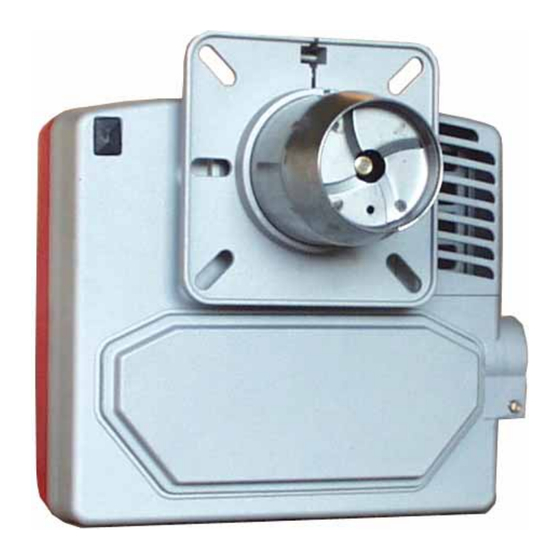
Light oil burners
Hide thumbs
Also See for IDEA Series:
- Manual of installation - use - maintenance (56 pages) ,
- Manual of installation - use - maintenance (52 pages)


Need help?
Do you have a question about the IDEA Series and is the answer not in the manual?
Questions and answers