Table of Contents

Related Manuals for Munters MCD100E


Summary of Contents for Munters MCD100E
- Page 1 Original instructions Users manual MCD100E, MCD120E, MCD140E, MCD155E Desiccant dehumidifier with electric heater for reactivation Applies to all units manufactured from week 22, 2013 190TEN–1065–J1408 © Munters Europe AB 2014...
-
Page 2: Important User Information
Important user information Intended use Safety Munters dehumidifiers are intended to be used for the Information about dangers are in this manual indicated dehumidification of air. Any other use of the unit, or by the common hazard symbol: use which is contrary to the instructions given in this... -
Page 3: Table Of Contents
Table of contents Important user information ....3.8.4 Duct connection dimensions for Intended use ......inlets ......Warranty . - Page 4 Scrapping ........7.3.1 Dimensions ....Contact Munters ......Table of contents...
-
Page 5: Introduction
1.1 General Munters manufactures a wide range of efficient dehumidifiers designed for different uses and applications. Contact your nearest Munters office if you have any questions regarding the installation or the use of your dehumidifier. For product data, see section Technical specification. - Page 6 OFF position before carrying out any service work. - Use only approved lifting equipment to prevent personal injury and damage to the equipment. - Always contact Munters for service or repair. WARNING! Never lift an assembled unit using lifting eye bolts attached to the top box. Lifting eye bolts must only be used for lifting the top box during installation of a split unit.
-
Page 7: Operation Monitoring
1.5 Operation monitoring The dehumidifier is controlled and monitored from the control panel on the front of the unit, see section 5.1, Control panel. The HMI (Human Machine Interface) is used to display values and parameters, and to input settings and commands to the control system. The HMI is described in the separate supplement. 1.6 Application limitations The dehumidifier conforms to the emission limits of residential, commercial and light-industrial environments except for the emission limits for harmonics emission (EN 61000–3–12). -
Page 8: Marking
3 ~ 400V 50Hz 102 kW 13,2 kW Max 115,9 kW IP33 Made in Sweden Munters Europe AB Isafjordsgatan 1 164 26 Kista, Sweden Figure 1.4 Position of identification plate Figure 1.5 Identification plate, example Explanation of "Fabr. no" on the identification plate:... -
Page 9: Dehumidifier Design
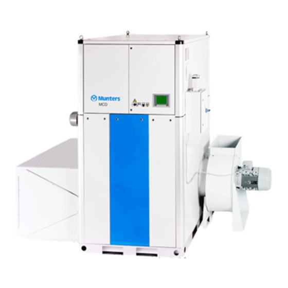
Dehumidifier design 2.1 Product description The desiccant dehumidifier has been designed to effectively dehumidify the air in environments requiring low air humidity. ® All functional components are enclosed in a corrosion resistant Aluzink casing (standard) or stainless steel casing (option) which makes installation and maintenance easy. The unit is constructed on a steel base frame which allows the use of a fork-lift truck during transportation and installation. - Page 10 1. Process air 2. Dry air 3. Reactivation air 4. Wet air Figure 2.2 Airflow overview Dehumidifier design 190TEN–1065–J1408...
-
Page 11: Main Components, Exploded View
2.3 Main components, exploded view Figure 2.3 Main components 1. Reactivation fan 7. Drive belt 2. Reactivation air filter 8. Rotor drive motor 3. Process fan 9. Rotor 4. Electrical panel 10. Filter box, process air 5. Reactivation heater 11. Filter box, process air (option) 6. -
Page 12: Configuration Features
2.4 Configuration features This chapter includes information about functions and components that can be added when ordering a MX² dehumidifier. At delivery, each unit is configured according to the configuration sheet supplied with the user manual. 2.4.1 Insulated process air inlet All dehumidifier units supplied with pre-cooled process air have insulated process air inlet. -
Page 13: Energy Recovery Purge
2.4.3 Energy Recovery Purge 1. Reactivation air 2. Heated reactivation air 3. Wet air 4. Process air 5. Dry air 6. Purge air 7. Warm purge air Figure 2.4 Principle for Energy Recovery Purge Energy Recovery Purge (ERP) is an energy saving solution that recycles heat from the rotor, after the reactivation section in the rotational direction of the rotor. -
Page 14: Installation
Installation 3.1 Safety WARNING! All electrical equipment connections must be carried out in accordance with local regulations and by qualified personnel. Risk of electrical shock. WARNING! The unit must never be connected to a voltage or frequency other than that for which it was designed. Refer to the unit identification plate. -
Page 15: Inspection Of Delivery
4. Remove all packaging material from the unit, and make sure that no damage has occurred during transportation. 5. Any visible damage must be reported in writing to Munters within 5 days and prior to installation of the unit. 6. Dispose of the packaging material according to local regulations. -
Page 16: Storing The Dehumidifier
Refer to Munters for advice if in doubt. NOTE! If there is a need for reduction of vibrations from the dehumidifier, contact Munters for instructions. Refer to standard EN1299+A1:2008. See section 7.3, Dimensions and service space for unit and service dimensions. - Page 17 Figure 3.3 Rotor box Figure 3.4 Top box Figure 3.5 Fans Figure 3.6 Filter box Figure 3.7 1. Reactivation fan 2. Process fan 3. Filter boxes Installation 190TEN–1065–J1408...
-
Page 18: Assembly
3.7.1 Assembly 1. Pull off the protection tape from the rotor box seals. 2. Make sure that the four lifting eye bolts for the top box are tightened. Figure 3.8 Lifting eye bolts for top box 3. Lift the top box onto the rotor box and make sure that the guide lips and M8 screws align in each corner, see Figure 3.9 . - Page 19 Figure 3.10 A: M8 screw seen from underneath. Figure 3.11 D: Cover plates 4. Tighten the four M8 screws (A) to compress the seals. 5. Fasten the two cover plates (D) with pop rivets (4 x 10 mm) . 6. Unscrew the lifting eye bolts from the top box to prevent lifting of the assembled unit. 7.
-
Page 20: Electrical Connections
3.7.2 Electrical connections 1. Install the infeed box and the cable for power supply. Figure 3.14 Power supply infeed box (E) 2. Connect the cables for the reactivation fan and process fan, see Figure 3.15 , Figure 3.16 and Figure 3.17 . Figure 3.15 Fan motor wiring Figure 3.16 Process fan Figure 3.17 Reactivation fan... - Page 21 Terminal block (drive motor) Drive motor cable Brown cable Brown cable 6 (yellow) 4 (blue) 2 (green) Table 3.1 Connections for rotor drive motor 4. Connect the HTCO and PT1000, see Figure 3.19 , Figure 3.20 and Figure 3.21 . Run the cables through the rubber grommet (F).
- Page 22 6. Connect the DPT (Differential Pressure Transmitter) for the reactivation fan. The bottom side of the DPT is marked with plus (+) and minus (-) at the two connections. – Connect the tube from the fan duct (before impeller) to plus (+). –...
-
Page 23: Duct Installation
3.8 Duct installation 3.8.1 General recommendations The connections for process and reactivation air are designed in accordance with the recommendations in ISO 13351. The rectangular duct connections contain tapped inserts for M8 screws. NOTE! The dehumidifier has been designed to operate at specific process airflows (corresponding to the fan sizes installed) and must not be directly connected to air-conditioning systems. -
Page 24: Duct For Outdoor Air Inlet
3.8.2 Duct for outdoor air inlet When bringing ambient air from outdoors into the dehumidifier, the inlet duct opening must be located sufficiently high above ground level to prevent dust and debris from entering. The ducting must be designed to prevent rain and snow from being drawn into the dehumidifier. The air inlet must be located away from possible contaminants such as engine exhaust gases, steam and harmful vapours. -
Page 25: Duct Connection Dimensions For Inlets
3.8.4 Duct connection dimensions for inlets MCD100-155E Figure 3.26 Reactivation air inlet 250 (5x) M8 (12x) 1250 1358 1358 1418 1408 Figure 3.27 Process air inlet Figure 3.28 Process air inlet (for installation with filter box) (for installation without filter box) C: Use hexagon head bolts (M8 x 25). -
Page 26: Duct Connection Dimensions For Fans
3.8.5 Duct connection dimensions for fans MCD100-155E (2x) M8 (12x) Figure 3.29 Process air outlet (dry air outlet) C: Use hexagon head bolts (M8 x 25). Installation 190TEN–1065–J1408... -
Page 27: Electrical Connections
MCD100-155E 140 (2x) 134 (2x) M8 (10x) M8 (8x) MCD120 MCD100 MCD140 MCD155 Figure 3.30 Reactivation air outlet (wet air outlet) C: Use hexagon head bolts (M8 x 25). 3.9 Electrical connections The dehumidifier is designed for operation with a three-phase four wire system. All dehumidifiers are delivered complete with all internal wiring installed and configured in accordance with the voltage and frequency specified on the identification plate. -
Page 28: External Humidity Transmitter
3.10 External humidity transmitter The dehumidifier is delivered with one of the humidity transmitters described below. The transmitter has an output signal of 4–20 mA for temperature and humidity respectively. Humidity transmitter for relative humidity in wall mounted version (standard): ■... -
Page 29: Commissioning
For more information about the control system, parameters and settings, see the control system supplement. Contact Munters for help with installation and settings. For contact addresses, see section 9, Contact Munters. NOTE! The application software settings for the frequency converter are set at the factory. The frequency control range is limited to correspond to an acceptable fan speed. -
Page 30: Setting The Rated Airflows
Failure to correctly adjust the airflows can cause malfunction of the unit. Any damage to the unit resulting from incorrect adjustment of the airflows can invalidate the warranty of the unit. The airflows must never be set above the rated airflows. If higher airflows are requested, consult Munters for verification. -
Page 31: Base Configuration Settings
EXAMPLE Reactivation air inlet temperature (ti): 15 °C Reactivation air temperature (to): 115 °C Temperature increase: 100 °C to = ti +100 °C 4.2.4 Base configuration settings Airflow Differential pressure Fan speed, coefficient (Pa) (rpm) 10000 1900 Process fan MCD- Reactivation fan 3060 2940... -
Page 32: Operation
Operation 5.1 Control panel ALARM SERVICE Figure 5.1 Control panel Figure 5.2 Main power switch Item Switch/Indicator Function Figure 5.2 Main power switch (see When the main power switch is in position 0, the unit is not powered beyond the switch. When the main power switch is in position 1, the dehumidifier can be started. -
Page 33: General
5.2 General The mode switch on the control panel has two operating positions: AUTO (Automatic position): The dehumidifier’s fans, rotor and reactivation heater are activated ■ only when the humidity exceeds the desired value (the set-point). If continual process air operation is selected in the control system display, the process air fan continues to run even after the unit has stopped dehumidifying. -
Page 34: Operating The Unit
5.5 Operating the unit 5.5.1 Initial start-up, Manual mode (MAN) 1. Set the main power switch to position 1 and check that the display lights up. 2. Set the mode switch to MAN position. Check that: The white lamp which indicates that the dehumidifier is in operational mode lights. A few seconds ■... -
Page 35: Service And Maintenance
This value is programmed by Munters personnel at initial start-up of the unit. Service and maintenance... -
Page 36: Service Options
Munters products. All test equipment used by our personnel to ensure proper system balancing is certified for accuracy. Munters Service can offer a service plan adapted to suit the conditions of a specific installation. See contact addresses on the back page of this manual. -
Page 37: (0-24000 Hours)
6.6 Service and maintenance schedule (0–24000 hours) Service level Start Service work Operating time in hours 4000 8000 12000 16000 20000 24000 Calendar time in months Filter inspection, replace filter if necessary, function controls Preventive inspection including safety check Capacity check, rotor inspection Replacement of high-temperature protection Inspection of heater coils Replacement of drive belt and belt fastener... -
Page 38: Service And Maintenance Schedule (28000-48000 Hours)
6.7 Service and maintenance schedule (28000–48000 hours) Service level Service work Operating time in hours 28000 32000 36000 40000 44000 48000 Calendar time in months Filter inspection, replace filter if necessary, function controls Preventive inspection including safety check Capacity check, rotor inspection Replacement of high-temperature protection Inspection of heater coils Replacement of drive belt and belt fastener... -
Page 39: Air Filter Replacement
6.9 Air filter replacement 6.9.1 Preparation 1. Set the mode switch to position 0. 2. Wait 60 seconds for the heater to cool down. 3. Set the main power switch to position 0 and lock the switch. 6.9.2 Reactivation air filter 1. -
Page 40: Process Air Filter
6.9.3 Process air filter 1. Unscrew the screws holding one of the covers (see Figure 6.5 ). Carefully remove the cover from the filter box without damaging the gasket. 2. Pull the channel spacers straight out from the filter box to release the filters, see Figure 6.6 . 3. -
Page 41: Technical Specification
Technical specification 7.1 Capacity diagrams Approximate capacity in kg/h. Contact your nearest Munter´s office for further information. NOTE! The figures in the diagrams are based on a rated airflow (1/1). MCD100 MCD120 kg/h kg/h 80 % RH 60 % RH 40 % RH 80 % RH 60 % RH... -
Page 42: Noise Data
7.2 Noise data 7.2.1 MCD100E Setup A: All ducts connected 1. Ductwork for dry air Setup B: Process inlet not connected to duct 2. Ductwork for process air Setup C: Reactivation inlet not connected to duct 3. Ductwork for reactivation air Setup D: Reactivation and process inlet not connected to duct 4. -
Page 43: Mcd120E
7.2.2 MCD120E Setup A: All ducts connected 1. Ductwork for dry air Setup B: Process inlet not connected to duct 2. Ductwork for process air Setup C: Reactivation inlet not connected to duct 3. Ductwork for reactivation air Setup D: Reactivation and process inlet not connected to duct 4. -
Page 44: Mcd140E
7.2.3 MCD140E Setup A: All ducts connected 1. Ductwork for dry air Setup B: Process inlet not connected to duct 2. Ductwork for process air Setup C: Reactivation inlet not connected to duct 3. Ductwork for reactivation air Setup D: Reactivation and process inlet not connected to duct 4. -
Page 45: Mcd155E
7.2.4 MCD155E Setup A: All ducts connected 1. Ductwork for dry air Setup B: Process inlet not connected to duct 2. Ductwork for process air Setup C: Reactivation inlet not connected to duct 3. Ductwork for reactivation air Setup D: Reactivation and process inlet not connected to duct 4. -
Page 46: Dimensions And Service Space
7.3 Dimensions and service space 7.3.1 Dimensions 1590 1303 Ø ( 64 (2X)) 3100 MCD100E MCD120E MCD140E MCD155E 1300 Figure 7.1 Dimensions D. Option Technical specification 190TEN–1065–J1408... -
Page 47: Dimensions For Units Without Process Fan
7.3.2 Dimensions for units without process fan Figure 7.2 Dimensions for units without process fan 7.3.3 Service space Figure 7.3 Required service space Technical specification 190TEN–1065–J1408... -
Page 48: Technical Data
7.4 Technical data MCD100E MCD120E MCD140E MCD155E Process air Figures quoted are rated, based on a fan inlet temperature of 20 °C and an air density of 1,2 kg/m Rated airflow (m 2,78 3,33 3,89 4,25 Rated airflow (m 10000... - Page 49 MCD100E MCD120E MCD140E MCD155E Weight Weight, rotor box and top box (kg Weight rotor box (kg) Weight, top box (kg) Weight, reactivation fan (kg) Weight, process fan (kg) Weight, filter box (kg) Weight, total (kg) 1132 1153 1153 1062 Weight, total, without process fan (kg)
-
Page 50: Scrapping
Scrapping The unit must be scrapped in accordance with applicable legal requirements and regulations. Contact your local authorities. The rotor material is not combustible, and should be deposited like glass fibre materials. If the rotor has been exposed to chemicals that are dangerous to the environment the risk must be assessed. The chemicals can accumulate in the rotor material. -
Page 51: Contact Munters
Munters Belgium nv Blarenberglaan 21c Tel: +3215285611 Air Treatment B-2800 Mechelen service@muntersbelgium.be www.muntersbelgium.be CZECH REPUBLIC Tel: +420 775 569 657 Munters CZ, organizacni slozka Slevacská 2368/68 info@munters-odvlhcovani.cz Air Treatment CZ-615 00 BRNO www.munters-odvlhcovani.cz DENMARK Munters A/S Ryttermarken 4 Tel: +4544953355... - Page 52 www.munters.com...
Need help?
Do you have a question about the MCD100E and is the answer not in the manual?
Questions and answers
were is electrical heater in this dehumidifier plz showing me location and how i can remove this heater.