Dometic D21 Service Manual
Hide thumbs
Also See for D21:
- Installation manual (4 pages) ,
- Installation and operating manual (28 pages) ,
- Installation and operating manual (12 pages)
Table of Contents
Advertisement
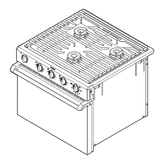
D21, DV20, DV30, R31, RA/RV 34, RA/RV 35, S31
Range
EN
Service Manual . . . . . . . . . . . . . . . . . . . . . . . .2
HOT PRODUCTS
RANGE
Form No. 51008_A 05/19 | ©2019 Dometic Corporation
WARNING: If the information in this manual is not followed
exactly, a fire or explosion may result, causing property
damage, personal injury, or death.
– Do not store or use gasoline or other flammable vapors
and liquids in the vicinity of this or any other appliance.
– WHAT TO DO IF YOU SMELL GAS
• Do not try to light any appliance.
• Do not touch any electrical switch.
• Do not use any phone in your recreational vehicle.
• Clear the recreational vehicle of all occupants.
• Turn off the gas supply tank valve(s) or main gas
supply.
• Immediately call your gas supplier for instructions.
• If you cannot reach your gas supplier, call the fire
department.
– Have the gas system checked and leakage source
corrected by a qualified installer, service agency,
manufacturer or dealer, or the gas supplier.
Advertisement
Table of Contents

Subscribe to Our Youtube Channel
Related Manuals for Dometic D21


Summary of Contents for Dometic D21
- Page 1 HOT PRODUCTS RANGE D21, DV20, DV30, R31, RA/RV 34, RA/RV 35, S31 Range WARNING: If the information in this manual is not followed Service Manual . . . . . . . . . . . . . . . . . . . . . . . .2 exactly, a fire or explosion may result, causing property damage, personal injury, or death.
-
Page 2: Table Of Contents
Service Center & Dealer Locations Checking the Gas Pressure ....20 Visit: www.dometic.com Straightening the Flex Line ....21 Read these instructions carefully. -
Page 3: Explanation Of Symbols And Safety
Indicates a hazardous situation that, if not avoided, injury: will result in death or serious injury. • Use only Dometic replacement parts and components, which are specifically approved for use WARNING with the appliance. -
Page 4: Intended Use
Readers of this manual are assumed to have a basic • Dometic gas-operated cooking units are for use with understanding of RV range best practices and liquid propane (LP) gas only in recreational vehicles... - Page 5 Range Troubleshooting Troubleshooting Table Operational Issue Potential Reason Page The pilot will not light or stay lit. The gas pressure is too low. The burner supply valve is closed. The orifice is blocked. The pilot assembly is blocked. There is a blockage or kink in the pilot line. The pilot flame is not engulfing the thermocouple.
- Page 6 The orifice to burner alignment is off. The ignition system fails to function. The Piezo or ignitor is defective. There is a faulty wire (D21 only). The burner is blocked. The gas pressure is too low. The cooktop is warped or blistered.
-
Page 7: General Information
DV = drop-in, Vision Number of Burners • • 4.1 Tools and Materials Revision Number • • Dometic recommends that the following tools and • materials be used while servicing the ranges: Cooktop Color • B = black • W = white Recommended Tools •... -
Page 8: Component Locations
General Information Range RA34/RA35 Models Door Color • B = black • G = black glass RA 21 3 2 - B S E • S = stainless steel • 1 = white Ignition Type • 2 = white glass Door Color •... - Page 9 Range General Information 1& 1 General Component Locations (models may vary) 2 RA/RV General Component Locations (models may vary) Grate Burner Supply Valve Grate Manifold Cooktop Oven Thermostat Cooktop Burner Supply Valve Control Knob Oven Door Control Knob Oven Thermostat Burner Head (Burner) Oven Flue (Vent) Burner Head (Burner)
-
Page 10: Wiring
Range 4.4 Wiring Term Definition The component of an appliance that Figure 3 shows the wiring for the D21 electronic ignition. Cooktop provides a surface for cooking. Can be stand-alone or part of a range. – The term describes the on/off operation of Cycling an appliance. -
Page 11: Diagnostic Procedures
Issues (on page 18) sections for more detail. Component Diagnostic Question Action Based On Status Page 12 VDC Ignition Module (D21 Model Only) Does the burner fail to ignite when the • Test the ignition at the burner: control knob is turned? Turn one control knob. - Page 12 Inspect the burner head. Is there visible If damage is observed, replace the component (visit damage (meltdown)? www.eDometic.com for service kit information and www.dometic.com for installation details). Burner Supply Valve Do the burner or pilots fail to light or stay •...
- Page 13 Are there any blockages in the line or Replace the component (visit www.eDometic.com visible damage to the line? for service kit information and www.dometic.com for installation details). Is there a constant gas smell present? Perform a spray leak test.
- Page 14 Ensure there is no wire damage. If damage is present, replace the wires. • If any of the parts are damaged, replace the component (visit www.eDometic.com for service kit information and www.dometic.com for installation details). Oven Burner Does the oven burner light, but the flame •...
- Page 15 Inspect the oven burner. Is there visible If damage is observed, replace the component (visit damage? www.eDometic.com for service kit information and www.dometic.com for installation details). Oven Door Seal Is excessive heat coming out from around If damage is observed, replace the component (visit the oven door? www.eDometic.com for service kit information and...
- Page 16 Inspect the thermostat. Is there visible If damage is observed, replace the component (visit damage? www.eDometic.com for service kit information and www.dometic.com for installation details). Piezo Ignitor Does the burner fail to ignite when the • Test the ignition at the burner: control knob is turned? Turn one control knob.
- Page 17 Inspect the pilot assembly. Is there visible If damage is observed, replace the component (visit damage? www.eDometic.com for service kit information and www.dometic.com for installation details). Thermal bulb Is the oven cooking foods unevenly • Realign the thermal bulb.
-
Page 18: Installation Issues
2. Place an illuminated 75 W light bulb under the warnings could result in death or serious injury. blanket. – Use only Dometic replacement parts and The temperature of the bottle should rise 10–20 °F [(-12)– components, which are specifically approved for (-7) °C] over a brief period of time, which increases tank... -
Page 19: Service Procedures
HAZARD. Failure to obey the following 6. Reverse the steps for re-installation. warnings could result in death or serious injury. – Use only Dometic replacement parts and 7.2 Accessing the Range components, which are specifically approved for Components for RA/RV Models use with the appliance. -
Page 20: Performing A Leak Test
Service Procedures Range 7.3 Performing a Leak Test 7.4 Checking the Gas Pressure 6 Spray Leak Test 7 Performing an LP Pressure Drop Leak Test The example figure for the spray leak test uses a Regulator Pressure Gauge burner supply valve for illustration purposes. The 1. -
Page 21: Straightening The Flex Line
Range Service Procedures A system pressure of 13-in. W.C. reaches the gauge 2. Locate the flex line. See Component Locations (on under a no-flow condition. Under flow conditions, page 8) for more detail. the pressure should read 10-in. W.C. 3. Gently manipulate the line until straightened. 6. -
Page 22: Testing The 12 Vdc Ignition Module
Range 7.7 Testing the 12 VDC Ignition Module 7.8 Cleaning and Clearing the Orifice This section applies to D21 models only. R31 models only 10 Testing the 12 VDC Ignition Module 1. Perform the steps in Accessing the Range Components (on page 19) before proceeding with service. -
Page 23: Clearing The Oven Flue (Vent)
Range Service Procedures RA/RV models only 7.9 Clearing the Oven Flue (Vent) 12 Clearing and Cleaning the Orifice Screw Burner Assembly 1. Perform the steps in Accessing the Range Components for RA/RV Models (on page 19) before proceeding with service. For RA Models, the burner will twist off when you 13 Clearing the Oven Flue (Vent) remove the cooktop. -
Page 24: Repositioning The Thermal Bulb
Service Procedures Range 7.10 Repositioning the Thermal Bulb 7.11 Aligning the Thermocouple 15 Aligning the Pilot and Thermocouple 14 Repositioning the Thermal Bulb 1. Open the oven door. 1. Open the oven door. 2. Locate the pilot assembly. See Component Locations 2. -
Page 25: Replacing The Oven Bulb
Range Service Procedures 7.12 Replacing the Oven Bulb 7.13 Replacing the Oven Light Switch and Wires This section applies to R31 models only. This section applies to R31 models only. 17 Removing the Oven Light Switch and Wires 1. Perform the steps in Accessing the Range Components (on page 19) before proceeding 16 Removing the Oven Bulb with service. -
Page 26: Maintenance
1. Turn the knob approximately 90° until it points to the warnings could result in death or serious injury. large flame decal. • Use only Dometic replacement parts and 2. Turn the spark ignitor knob clockwise until it clicks. components, which are specifically approved for use with the appliance. -
Page 27: Cleaning
2. Clean with warm, soapy water. For the most current parts information, visit www. 3. Rinse with clean water. dometic.com. 4. Dry with a soft cloth. Heavy burned-on soil may require repeated cleaning steps until the soil is completely removed. - Page 28 Mobile living made easy. dometic.com YOUR LOCAL YOUR LOCAL YOUR LOCAL DEALER SUPPORT SALES OFFICE dometic.com/dealer dometic.com/contact dometic.com/sales-offices...
Need help?
Do you have a question about the D21 and is the answer not in the manual?
Questions and answers
I have a dometic D21 cooktop. One burner has very low gas flow, very low flame. Originally it was fine.
The gas flow is low and the flame is weak on the Dometic D21 cooktop burner due to one or more of the following reasons:
- The burner is blocked.
- The gas pressure is too high or too low.
- The air/gas mixture is incorrect.
- The orifice is blocked.
- There is a problem with the burner supply valve.
- There is an installation issue.
This answer is automatically generated