Table of Contents
Advertisement
Quick Links
Advertisement
Table of Contents

Subscribe to Our Youtube Channel
Related Manuals for ADJ JOLT BAR FX2


Summary of Contents for ADJ JOLT BAR FX2
- Page 1 JOLT BAR FX2 User Manual...
- Page 2 ©2024 ADJ Products, LLC all rights reserved. Information, specifications, diagrams, images, and instructions herein are subject to change without notice. ADJ Products, LLC logo and identifying product names and numbers herein are trademarks of ADJ Products, LLC. Copyright protection claimed includes all forms and matters of copyrightable materials and information now allowed by statutory or judicial law or hereinafter granted.
-
Page 3: Table Of Contents
C O N T E N T S Introduction Limited Warranty (USA Only) Warranty Registration | Features Safety Guidelines Overview Lens Installation Installation Guidelines Fan Modes and Low Noise Operation System Menu Dimmer Modes and Curves DMX Setup DMX Traits Color Temperature Color Macro Chart Remote Device Management (RDM) -
Page 4: Introduction
Please do not discard the shipping carton in the trash. Please recycle whenever possible. FOR SOFTWARE UPDATES, CONTACT ADJ CUSTOMER SUPPORT. CUSTOMER SUPPORT Contact ADJ Service for any product related service and support needs. Also visit forums.adj.com with questions, comments or suggestions. -
Page 5: Limited Warranty (Usa Only)
All shipping charges must be pre-paid. If the requested repairs or service (including parts replacement) are within the terms of this warranty, ADJ Products, LLC will pay return shipping charges only to a designated point within the United States. If the entire instrument is sent, it must be shipped in its original package. No accessories should be shipped with the product. -
Page 6: Warranty Registration | Features
WA R R A N T Y R E G I S T R AT I O N The Jolt Bar FX2 carries a 2 year limited warranty. Please fill out the enclosed warranty card to validate your purchase. All returned service items, whether under warranty or not, must be freight pre-paid and accompanied by a return authorization (R.A.) number. -
Page 7: Safety Guidelines
THIS FIXTURE IS COMPOSED OF SOPHISTICATED ELECTRONIC COMPONENTS. TO GUARANTEE SMOOTH OPERATION, IT IS IMPORTANT TO FOLLOW ALL INSTRUCTIONS AND GUIDELINES IN THIS MANUAL. ADJ PRODUCTS, LLC IS NOT RESPONSIBLE FOR INJURY AND/OR DAMAGES RESULTING FROM THE MISUSE OF THIS FIXTURE DUE TO THE DISREGARD OF THE INFORMATION PRINTED IN THIS MANUAL. -
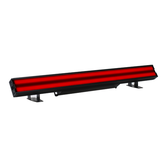
Page 8: Overview
O V E R V I E W Mounting Bracket D D M M X X I I N N D D M M X X O O U U T T P P r r o o d d u u c c t t I I D D : : J J O O L L 2 2 8 8 6 6 M M o o d d e e l l : : J J o o l l t t B B a a r r F F X X 2 2 N N o o t t f f o o r r r r e e s s i i d d e e n n t t i i a a l l u u s s e e I I n n p p u u t t P P o o w w e e r r : : A A C C 1 1 0 0 0 0 - - 2 2 4 4 0 0 V V , , 5 5 0 0 - - 6 6 0 0 H H z z N N o o n n d d e e s s t t i i n n é... -
Page 9: Lens Installation
L E N S I N S TA L L AT I O N Locate Frost Filter Lens Lock and press down to unlock it. Carefully slide Frost Filter Lens into the Lens Slots. Once in place, secure the Frost Filter Lens by pressing upwards to relock it. - Page 10 I N S TA L L AT I O N FLAMMABLE MATERIAL WARNING Keep fixture minimum 5.0 feet (1.5m) away from flammable materials and/or pyrotechnics. ELECTRICAL CONNECTIONS A qualified electrician should be used for all electrical connections and/or installations. MINIMUM DISTANCE TO OBJECTS/SURFACES IS 6.6 FEET (2 METERS). MINIMUM DISTANCE OF INFLAMMABLE MATERIALS FROM THE SURFACE IS 1.6 FEET (0.5 METERS).
- Page 11 I N S TA L L AT I O N CLAMP INSTALLATION This fixture features a brackets for the attachment of a mounting clamp. There is also a safety cable loop located on the heatsink rear of encased controller). When mounting the fixture to a truss or any other suspended or overhead installation, be sure to secure appropriately rated clamps (not included) to the yoke, and attach a separate SAFETY CABLE of the appropriate weight rating to the safety cable loop.
-
Page 12: Installation Guidelines
I N S TA L L AT I O N G U I D E L I N E S OMEGA BRACKETS INSTALLATION Remove adjustable brackets and replace them with Omega Receiver Brackets. Insert the Omega Brackets into the matching holes on the Omega Receiver Brackets. Secure the Omega Brackets by turning each quick-lock fastener ¼... - Page 13 I N S TA L L AT I O N CONNECTOR PLATE: Each unit includes a connector plate that can be used to secure two adjacent mounted units together. To install the connector plate, follow the directions below: Place the connector plate across the gap between the two units, making sure to align the plate with the four (4) screw holes.
- Page 14 I N S TA L L AT I O N G U I D E L I N E S RIGGING Overhead rigging requires extensive experience, including among others, calculating working load limits, installation material being used, and periodic safety inspection of all installation material and the fixture.
- Page 15 I N S TA L L AT I O N G U I D E L I N E S POTENTIAL INTERNAL FIXTURE DAMAGE FROM EXTERNAL SOURCES OF LIGHT BEAMS External sources of light beams from direct sunlight, lighting and moving head fixtures, and lasers, which are focused directly towards the exterior housing and/or penetrate the front lens opening of Elation lighting fixtures, can cause severe internal damage including burning of optics, dichroic color filters, glass and metal gobos, prisms, animation wheels, frost filters, iris, shutters, motors, belts,...
-
Page 16: Fan Modes And Low Noise Operation
FA N M O D E S a n d L O W N O I S E O P E R AT I O N The Jolt Bar FX2 is a high-performance fixture suited for multiple applications. For noise critical environments such as Theater, Opera or Orchestra Halls, it offers various fan operation modes which remove any distraction for the audience and performers. -
Page 17: System Menu
S Y S T E M M E N U The fixture includes an easy to navigate system menu control panel display where all necessary settings and adjustments are made. • MENU: Leave current menu and return to previous menu level. •... - Page 18 S Y S T E M M E N U MAIN MENU OPTIONS / VALUES (Default Settings in BOLD) DESCRIPTION DMX Address 001 - 512 6CH, 9CH, 13CH, 16CH, 18CH, 32CH, 38CH, DMX Settings DMX Mode 43CH, 64CH, 78CH, 112CH, 127CH Hold Last, Blackout, Manual No DMX Status Primary, Secondary...
- Page 19 S Y S T E M M E N U MAIN MENU OPTIONS / VALUES (Default Settings in BOLD) DESCRIPTION 000-255 Green 000-255 Blue 000-255 White 000-255 000-255 Manual Green Shift 000-255 RGB Shutter 000-255 000% - 100% RGBDimmer White Shutter 000-255 Whited Dimmer 000% - 100%...
-
Page 20: Dimmer Modes And Curves
D I M M E R M O D E S A N D C U R V E S... -
Page 21: Dmx Setup
2 and 3 of a male XLR connector (DATA + and DATA -). This unit is inserted in the female XLR connector of the last unit in your daisy chain to terminate the line. Using a cable terminator (ADJ part number Z-DMX/T) will decrease the chances of erratic behavior. - Page 22 D M X S E T U P DMX ADDRESSING All fixtures should be given a DMX starting address when operating with a DMX controller, in order to ensure that the correct fixture responds to the correct control signal. This digital starting address is the channel number from which the fixture starts to “listen” to the digital control signal sent out from the DMX controller. The assignment of this starting DMX address is achieved by setting the correct DMX address on the digital control display on the fixture. You can set the same starting address for all fixtures or a group of fixtures, or set different addresses for each individual fixture. Setting all fixtures to the same DMX address will cause all fixtures to react in the same way. In this case, please note that changing the settings of one channel will affect all the fixtures simultaneously. If you set each fixture to a different DMX address, each unit will “listen” starting at the channel num- ber you have set, based on the quantity of DMX channels of each fixture. That means changing the settings of one channel will only affect the selected fixture. As an example, when operating this device in 6 channel mode, you should set the starting DMX address of the first unit to 1, the second unit to 7 (1 + 6), the third unit to 13 (1 + 6 + 6), and so on. (See the chart below for more details.) Channel Mode Unit 1 Address Unit 2 Address Unit 3 Address Unit 4 Address 6 Channels 9 Channels 13 Channels 16 Channels...
-
Page 23: Dmx Traits
D M X T R A I T S CHANNEL FUNCTION VALUES Outer Red , 0% - 100% 000-255 Outer Green , 0% - 100% 000-255 Outer Bkue , 0% - 100% 000-255 Inner White, 0% - 100% 000-255 Inner White Group 1 000-255 Inner White Group 2 000-255... - Page 24 D M X T R A I T S CHANNEL FUNCTION VALUES Outer Program Macro 000-005 No function 006-015 Macro 1 016-025 Macro 2 026-035 Macro 3 036-045 Macro 4 046-055 Macro 5 056-065 Macro 6 066-075 Macro 7 076-085 Macro 8 086-095 Macro 9...
- Page 25 D M X T R A I T S CHANNEL FUNCTION VALUES Inner Strobe Effect 000-002 Open 003-005 Strobe 006-050 Ramp up 051-100 Ramp down 101-150 Ramp up-down 151-200 lightning 201-255 Random 000-255 Inner Strobe Rate, slow to fast 000-255 Inner Strobe Duration, slow to fast Inner Program Macro 000-005...
- Page 26 D M X T R A I T S CHANNEL FUNCTION VALUES Red 1 000-255 Green 1 000-255 000-255 Blue 1 000-255 Red 2 Green 2 000-255 Blue 2 000-255 Red 3 000-255 000-255 Green 3 000-255 Blue 3 Red 4 000-255 Green 4 000-255...
- Page 27 D M X T R A I T S CHANNEL FUNCTION VALUES Red 14 000-255 Green 14 000-255 000-255 Blue 14 000-255 Red 15 Green 15 000-255 Blue 15 000-255 Red 16 000-255 000-255 Green 16 000-255 Blue 16 Red 17 000-255 Green 17 000-255...
- Page 28 D M X T R A I T S CHANNEL FUNCTION VALUES Red 26 000-255 Green 26 000-255 000-255 Blue26 000-255 Red 27 Green 27 000-255 Blue 27 000-255 Red 28 000-255 000-255 Green 28 000-255 Blue 28 Red 29 000-255 Green 29 000-255...
-
Page 29: Color Temperature
C O LO R T E M P E R AT U R E DMX VALUE COLOR TEMPERATURE (K) DMX VALUE COLOR TEMPERATURE (K) 2300 6200 2400 6300 2500 6400 2600 6500 2700 6600 2800 6700 2900 6800 3000 6900 3100 7000 3200... -
Page 30: Color Macro Chart
C O L O R M A C R O C H A R T Macro Nmnber DMX VALUE No Function 000-009 Color1 010-017 Color2 018-024 Color3 025-032 Color4 033-039 Color5 040-047 Color6 048-054 Color7 055-061 Color8 062-069 Color9 070-076 Color10 077-084 Color11... -
Page 31: Remote Device Management (Rdm)
R E M O T E D E V I C E M A N A G E M E N T ( R D M ) NOTE: for RDM to work properly, RDM enabled equipment must be used throughout the entire system, including DMX data splitters and wireless systems. -
Page 32: Led Pixel Zones
L E D P I X E L Z O N E S 6CH, 9CH, 13CH, AND 18CH MODES Outer Inner Outer 16CH MODE RGB1 RGB2 White White2 White3 White4 RGB3 RGB4 32CH MODE RGB1 RGB2 RGB3 RGB4 White1 White2 White3 White4 White5... -
Page 33: Daisy Chain Power Linking | Cleaning And Maintenance
Regular inspections are recommended to ensure proper function and extended life. There are no user serviceable parts inside this fixture. Please refer all other service issues to an authorized ADJ service technician. Should you need any spare parts, please order genuine parts from your local ADJ dealer. -
Page 34: Specifications
S P E C I F I C AT I O N S Light Source: • 448 x 0.5W RGB SMD LEDs + 112 x 5W Cool White SMD LEDs • 78° Beam Angle • 117° Field Angle • Color Temperature: Red: 620-630nm. Green: 515-525nm. Blue: 460-470nm. / Cool White: 6900- 7400K •... -
Page 35: Dimensions
D I M E N S I O N S Dimensions are not drawn to scale. 3.5in. [90mm] 1.7in. [43mm]...
Need help?
Do you have a question about the JOLT BAR FX2 and is the answer not in the manual?
Questions and answers