Table of Contents
Advertisement
Quick Links
EMH metering
GmbH & Co. KG
Neu-Galliner Weg 1 • 19258 Gallin
GERMANY
Tel.
+49 38851 326-0
Fax
+49 38851 326-1129
Email info@emh-metering.com
Web
www.emh-metering.com
Tel.
+49 38851 326-1930 (Technical Support)
Email support@emh-metering.com
XC-RACK
Digital 4-quadrant/combi meter
EN
Instructions for use
Scope of delivery .................................................................................... 2
Important information.............................................................................. 2
Target group........................................................................................ 2
Intended use ....................................................................................... 3
Maintenance and warranty instructions .............................................. 3
Care and disposal instructions............................................................ 3
Basic safety instructions ..................................................................... 5
Notes on correctness of measurements ............................................. 5
Technical data......................................................................................... 6
Housing, display and control elements ................................................... 7
Name plate ......................................................................................... 8
Display ................................................................................................ 9
Installation and start-up .........................................................................11
Mounting and connecting the meter ................................................. 12
Variants for connection of the meter ................................................. 14
Installation control register C.86.0 (optional) .................................... 18
Error register F.F ............................................................................... 20
Abbreviations ........................................................................................ 21
EU Declaration of Conformity ............................................................... 23
Issue date: 06 October 2023; subject to technical changes.
XC-RACK-BIA-E-1.80
Advertisement
Table of Contents

Subscribe to Our Youtube Channel
Related Manuals for EMH metering XC-RACK


Summary of Contents for EMH metering XC-RACK
-
Page 1: Table Of Contents
EMH metering GmbH & Co. KG Neu-Galliner Weg 1 • 19258 Gallin GERMANY Tel. +49 38851 326-0 +49 38851 326-1129 Email info@emh-metering.com www.emh-metering.com Tel. +49 38851 326-1930 (Technical Support) Email support@emh-metering.com XC-RACK Digital 4-quadrant/combi meter Instructions for use Scope of delivery ..................2 Important information................ -
Page 2: Scope Of Delivery
Scope of delivery Please check the contents of the packing box are complete before starting with the installation and start-up procedure. y 1 XC-RACK device y 1 Instructions for use If the contents are incomplete or damaged, please contact your supplier. -
Page 3: Intended Use
Intended use The meter is intended to be used solely for the measurement of elec- trical energy in inside spaces, and it must not be operated outside the specified technical data (see name plate). Make sure that the meter is suitable for the intended application. Maintenance and warranty instructions The device requires zero maintenance. - Page 4 Components Waste collection and disposal Electronic waste: Dispose of such waste in Printed circuit boards accordance with the local regulations. LEDs, Hazardous waste: Dispose of such waste in LC displays accordance with the local regulations. Recyclable material: Sort such material and send it Metal parts for recycling.
-
Page 5: Basic Safety Instructions
If the mains power fails and then returns, there is no need to do anything to the meter. Notes on correctness of measurements For the notes on correctness of measurements applicable to this meter, please see the enclosed document entitled “Notes on correctness of measurements for LZQJ-XC, DMTZ-XC and XC-RACK”. -
Page 6: Technical Data
Technical data Voltage, current, frequency See name plate Overvoltage category OVC III (as per EN 62052-31) Rated peak withstand voltage 4 kV (as per EN 62052-31) Input max. 1, max. 27 V DC, 27 mA Low voltage or max. 8, 18…40 V DC system voltage max. -
Page 7: Housing, Display And Control Elements
Housing, display and control elements 1 - Name plate 2 - Display 3 - Optical call sensor 4 - Test LED (permanently on = no energy consumption or incorrect current direction) 5 - Reset button (sealable) 6 - Call-up button 7 - Optical data interface (D0) with recess for the readout unit 8 - Transformer plate (sealable) -
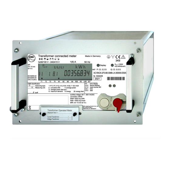
Page 8: Name Plate
Name plate 1 - Registered quadrants 2 - Type designation 3 - Voltage, current, frequency 4 - Safety and application information 5 - Conformity and certification marking 6 - Operating temperature 7 - Optical call sensor 8 - Test LED 9 - Accuracy class 10 - Type code 11 - Serial number... -
Page 9: Display
(optical or electrical) is communicating with the meter. The communication display flashes when parametrisation mode is active. On an XC-Rack with an LMN interface, this display lights up at irregular intervals as internal communications take place to provide the data for collection by an SMGW. - Page 10 4. The phase display indicates when individual phase voltages are applied. All 3 symbols flash when the rotating field is wrong. 5. The unit shown matches the type of energy being measured or the measurement being displayed. 6. The additional cursor field displays the operating states for the meter.
-
Page 11: Installation And Start-Up
Installation and start-up DANGER Risk of fatal injury in case of contact with live parts! During installation or when replacing the meter, the wires connected to the meter must be de-energised. y The installer bears responsibility for coordinating the rated values and parameters of the supply-side overcurrent protection devices with the maximum rated currents of the meter. -
Page 12: Mounting And Connecting The Meter
DANGER Risk of fatal injury in case of contact with live parts! In older versions up to and including those manufactured in 2023, S0 inputs are not potential-free. Depending on the voltage version of the device, the S0 inputs are connected electronically internally with the measuring connections or with the auxiliary voltage and are therefore not potential-free. - Page 13 ATTENTION Application of excessive torque will damage the connection terminals! The appropriate torque is dependent on the type of connection line involved and its maximum current. y Make sure that the screws of the connection terminals are undam- aged and smooth-running before starting the screwing process. y Tighten the connection terminals to the corresponding torque as per EN 60999-1.
-
Page 14: Variants For Connection Of The Meter
Transformer connected meter for connection to current and voltage transformers in three-wire systems (Aron circuit, M7 left and M8 right) 3020 The connections of the meter are on the back of the meter. Variants for connection of the meter DANGER Risk of fatal injury from excess voltages on the terminals of the current paths! The voltages on the terminals of the current paths must not be higher... - Page 15 a) Meter with Essailec connection system 1 - Communication interface 2 - Fibre optic interface DANGER Risk of fatal injury in case of contact with live parts! During installation of the Essailec connection system, it must be ensured that the PE connection (protective conductor) is connected first when the meter is plugged in, and that it is only removed during unplugging after the voltage connections have been disconnected.
- Page 16 Contact Meaning Contact Meaning RS485 B+ A+ GND RS485 A- A+ pulses RS485 GND R+ pulses S0− R+ GND A− pulses MPA+ A− GND MPA- R− pulses R− GND Contact Meaning Contact Meaning N = Neutral A1 - A01 Current phase 1 Voltage phase 1 A2 - A02 Current phase 2...
- Page 17 The Essailec contact assignment is variable and can be defined cus- tomer-specifically as shown in the previous example. The pin assignment of the sub-D connector is predetermined and can- not be modified: Contact Meaning RS485 B+ RS485 A− c) Meter with Phoenix screw-type terminals 90 94 93 92 91 40 44 43 42 41 11 8 21 20 28 27 37 35...
-
Page 18: Installation Control Register C.86.0 (Optional)
The contact assignment is variable and can be defined customer- specifically. Example: Contact Meaning Contact Meaning Current phase 1 In Current phase 1 Out Current phase 2 In Current phase 2 Out Current phase 3 In Current phase 3 Out Voltage phase 1 Voltage phase 2 S0−... - Page 19 C.86.0 (0 0 0 0 0 0 0 0) Not assigned Wrong rotating field Phase failure Negative power direction Current interruption Limiting current exceeded Undervoltage Overvoltage Event Value Meaning Wrong rotating field Failure of neutral conductor Wrong rotating field Current imbalance, e.g. 30% Voltage imbalance, e.g.
-
Page 20: Error Register F.f
Event Value Meaning Undervoltage Undervoltage L1 (U < 80%) Undervoltage L2 Undervoltage L3 Overvoltage Overvoltage L1 (U > 115%) Overvoltage L2 Overvoltage L3 Error register F.F The meter has 32 error flags that are represented by an 8-digit HEX number. This register records the function errors of the meter. The output of the error register is performed via the display and one of the read-out lists. -
Page 21: Abbreviations
Abbreviations Active energy Positive active energy (customer obtains from utility company) −A Negative active energy (customer exports to utility company) Accuracy class COSEM Companion Specification for Energy Metering Optical interface as per IEC 62056-21 DHCP Dynamic Host Configuration Protocol (dynamic assignment of IP addresses) Deutsches Institut für Normung e.V. - Page 22 OBIS Object Identification System (code for identification of measurements/data) Optical communication unit Overvoltage category Active power Positive active power (customer obtains from utility company) −P Negative active power (customer exports to utility company) Protective Earth, protective conductor Physikalisch-Technische Bundesanstalt (National Metrology Institute of Germany) Reactive power Positive reactive power...
-
Page 23: Eu Declaration Of Conformity
EU Declaration of Conformity You will find the current EU Declaration of Conformity on the in- ternet site www.emh-metering.com in the “Products & Solutions” area in the product description for the meter. The specifications for creating the Declaration of Conformity can change at any time, so back up the Declaration of Conform- ity when the device is delivered.
Need help?
Do you have a question about the XC-RACK and is the answer not in the manual?
Questions and answers