Table of Contents
Advertisement
EMH metering
GmbH & Co. KG
Neu-Galliner Weg 1 • 19258 Gallin
GERMANY
Tel.
+49 38851 326-0
Fax
+49 38851 326-1129
Email info@emh-metering.com
Web
www.emh-metering.com
Tel.
+49 38851 326-1930 (Technical Support)
Email support@emh-metering.com
LZQJ-SGM transformer connected meter
Digital 4-quadrant/combination meter
EN
Instruction Manual
Scope of delivery .................................................................................... 2
Important information.............................................................................. 2
Technical data......................................................................................... 5
Housing, display and control elements ................................................... 7
Installation and start-up ........................................................................ 13
Functions and operation ....................................................................... 20
Installation control register C.86.0 ........................................................ 31
Error register F.F ................................................................................... 33
COMBI-MASTER 2.0 configuration and read-out program ................. 34
Communication module ........................................................................ 35
Abbreviations ........................................................................................ 36
EU Declaration of Conformity ............................................................... 38
Issue date: 19 November 2021; subject to technic al changes.
LZQJ-SGM2-IM-E-1.04
Advertisement
Table of Contents

Related Manuals for EMH metering LZQJ-SGM


Summary of Contents for EMH metering LZQJ-SGM
-
Page 1: Table Of Contents
+49 38851 326-1129 Email info@emh-metering.com www.emh-metering.com Tel. +49 38851 326-1930 (Technical Support) Email support@emh-metering.com LZQJ-SGM transformer connected meter Digital 4-quadrant/combination meter Instruction Manual Scope of delivery ..................2 Important information................2 Technical data..................5 Housing, display and control elements ........... 7 Installation and start-up ................ -
Page 2: Scope Of Delivery
Scope of delivery Please check that the contents of the packing box are complete before starting the installation and start-up procedure. y 1 LZQJ-SGM device y 1 operating instructions y Connection diagram y Accessory (optional) If the contents are incomplete or damaged, please contact your supplier. - Page 3 Target audience These instructions are intended for technicians who are responsible for the installation, connection and servicing of the devices. The device may only be installed and started up by qualified electricians in accordance with the generally accepted technology standards and, where applicable, the definitive regulations governing the erection of communication equipment and terminal devices.
- Page 4 Care and disposal information DANGER Risk of fatal injury in case of contact with live parts! Before the housing of the meter is cleaned, all conductors that the meter is connected to must be de-energised. Use a dry cloth to clean the device housing. Do not use any chemical cleaning agents! The following table names the components and how they are to be treated at the end of their life cycle.
-
Page 5: Technical Data
Notes on correctness of measurements For the notes on correctness of measurements applicable to this meter in Germany, please see the enclosed document enti- tled “Notes on correctness of measurements for LZQJ-SGM.” Technical data Voltage, current, See name plate... - Page 6 Data interfaces Optical Optical data interface D0 (38400 baud), as per EN 62056-21 Electrical RS232 (115200 baud), as per ANSI EIA/TIA-232-F (R1997) RS485 (115200 baud), as per ANSI/TIA/EIA-485-A-98 (R2003) CL0 (19200 baud), as per DIN 66348-1 Output Optocoupler MOSFET max. 250 V AC/DC, max. 100 mA Power consumption per phase as per EN 62053-61 Ba se meter...
-
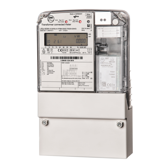
Page 7: Housing, Display And Control Elements
Housing, display and control elements 1 - Name plate 2 - Test LED for reactive power 3 - LC display 4 - Test LED for active power 5 - Optical call sensor (optional) 6 - Meter cover 7 - Sealing screw 8 - Optical data interface D0 9 - Call-up button 10 - Transformer plate (only for transformer connected meters) - Page 8 Optical call sensor: Used to call up the display lists on the display. The sensor is operated with a focussing torch. Optical data For communication between meter and interface D0: read-out device by means of an optical communication unit (OKK). You will find more information on the optical data inter- face in the user manual.
- Page 9 Name plate (example) 1 - Year of construction 2 - Test LED for reactive power 3 - Serial number 4 - Test LED for active power 5 - Product standard 6 - Optical call sensor 7 - Overvoltage category 8 - Accuracy class 9 - Operating temperature 10 - Space for ownership labelling 11 - Information about connection of the meter...
- Page 10 The name plate contains data for identification of the meter, the registra- tion mark, and technical specifications and explanations. The cursor labelling below the display and the description of the OBIS code numbers on the name plate are designed as standard and not adapted to the meter version.
- Page 11 LC display The LZQJ-SGM is equipped with a liquid crystal (LC) display as per VDEW specifications 2.1. 1. The operation display shows the energy direction that is currently being measured by the meter (supply/draw of active power, inductive/ capacitive reactive power). If a load current is flowing, the energy direction arrow indicates which quadrant is being used for the measurement, e.g.:...
- Page 12 5. The unit shown matches the type of energy being measured or the measured value displayed. 6. The additional cursor field displays the operating states for the meter. The arrows indicate whether any manipulation or an installation error was registered or if the power threshold was exceeded. The cursor is active where any manipulation of the terminal cover or meter cover or any magnetic influence is registered.
-
Page 13: Installation And Start-Up
Installation and start-up The meters in series LZQJ-SGM are suitable for wall mounting as per DIN 43857-2. When connecting the meter, always observe the corresponding connec- tion diagram, which is located on the meter’s name plate and in the delivery documents. - Page 14 DANGER Risk of fatal injury in case of contact with live parts! During installation or when replacing the meter, the wires connected to the meter must be de-energised. y The installer bears responsibility for coordinating the rated values and parameters of the supply-side overcurrent protection devices with the maximum rated currents of the meter.
- Page 15 Transformer Current and voltage Additional connected meter terminals terminals Terminal dimensions 5.3 x 5.5 2.6 x 2.2 W x H or d (mm) Minimum connection cross sections (mm²) Maximum connection cross sections (mm²)* Minimum torques — (Nm) Maximum torques — (Nm) Cross slot combination screw Spring-loaded...
- Page 16 View from below (maximum terminal assignment, specifications in mm) DANGER Risk of fatal injury from high voltage when power transformers disconnected! In transformer connected meters, the high voltage generated on a disconnected power transformer can cause fatal injuries and result in electric arcs on the terminal block.
- Page 17 If necessary, the secondary side of the voltage transformers must be earthed. Connection to current and voltage terminals Proceed as follows when connecting the LZQJ-SGM: 1. Ensure that all lines are free from voltage. 2. Shorten the conductors to the necessary length if necessary.
- Page 18 4. Push the lever of the spring-loaded terminal down with the screwdriver until the terminal opens. 5. Insert the line into the open terminal up to its insulation. Ensure that the cable insulation is not put inside the terminal. 6. Remove the screwdriver to allow the terminal to close.
- Page 19 You will find further connection diagrams as per DIN 43856 in the user manual. In addition to the connection diagram for current and voltage, the type plate contains information on the interfaces, such as the maximum voltage of the outputs, for example. The interfaces are marked with numbers, which can be found above the matching terminals in the terminal block area.
-
Page 20: Functions And Operation
0.5 Nm. Functions and operation For a detailed description on operating the LZQJ-SGM by means of a PC connected to the meter, please see the chapter on the COMBI- MASTER 2.0 in the user manual. The following sections describe only the procedure using the buttons on the device itself. - Page 21 Operation display (alternating display) The operation display is the default display. Data are displayed here in sequence with a gap of 10 s (scrolling) as default. Operation display Menu item Display Button Go to display Operation test display ( scrolling) t <...
- Page 22 From the display test, you can go to the call-up button menu or the reset button menu by pressing the call-up button or the reset button for less than 2 s. Display test Menu item Display Button Go to call-up Display test button menu mode (display...
- Page 23 Call-up button menu Menu item Display Button Activation Next menu of the load item profile list t < 2 s Enter the load profile list 2 s < t < 5 s End of display Return to menu item 1 t <...
- Page 24 Call list Menu item Display Button Next register Next menu item t < 2 s Pre-value Next menu item t < 2 s Repeat items 3 and 4 to display further registers/pre-values End of the de- Return to fault data list item 2 t <...
- Page 25 y Two measuring or registration period lengths (generally 30 min) after the last time a button is pressed, the system automatically returns to the operation display. You can also do this by pressing the call-up button for more than 5 s. This ensures that you can observe the progress of a complete registration period at minimum on the display.
- Page 26 Load profile list (default LP) Menu item Display Button Time of last- Next menu but-one entry item for selected t < 2 s End of the Return to load profile list item 4 t < 2 s Return to item 3 2 s <...
- Page 27 Reset button menu Menu item Display Button Operation Next menu display item ( scrolling) t < 2 s Display test Go to call-up button menu mode t < 2 s Go to reset button menu t < 2 s Activation of Next menu the adjustment item...
- Page 28 Reset button menu Menu item Display Button End of display Return to menu item 3 t < 2 s Return to item 3 2 s < t <5 s Go to opera- tion display t > 5 s Adjustment list (SEt) In the adjustment list it is possible to modify adjustable values by means of the call-up and reset button.
- Page 29 Adjustment list Menu item Display Button Next adjust- Edit first digit ment value (here: date in the format t < 2 s YY•MM•DD) Edit the first Increase digit digit (digit by 1 flashing) t < 2 s Edit next digit t <...
- Page 30 To display additional menu items, press the call-up button for less than 2 s. y To skip pre-values in order to call up data quickly, press the call-up button for more than 2 s and less than 5 s. y The end of the menu is indicated by the End menu item. y Two measuring or registration period lengths (generally 30 min) after the last time a button is pressed, the system automatically returns to the operation display.
-
Page 31: Installation Control Register C.86.0
Installation control register C.86.0 The installation control register C.86.0 registers installation errors. As a rule it is displayed on the alternating display or can be called up using the information list in the reset button menu. The monitored measured values result from the instantaneous values. If the meter was installed without errors, the register contains the value “00000000”. - Page 32 Event Value Meaning Manipulation detection Manipulation of the meter cover Manipulation of the terminal cover Manipulation through magnetic fields Wrong rotating field Failure of neutral conductor Wrong rotating field Phase failure Phase failure L1 Phase failure L2 Phase failure L3 Failure of the external power supply Negative power direction Negative power direction L1 (P)
-
Page 33: Error Register F.f
Error register F.F The LZQJ-SGM is equipped with an error register that records the func- tion errors of the meter. The output of the error register is performed via the display and the read-out lists. If an error is displayed, the meter data can no longer be used as a basis for billing. -
Page 34: Combi-Master 2.0 Configuration And Read-Out Program
For a detailed description of the COMBI-MASTER 2.0, please see the relevant chapters in the user manual. The program is used to configure the LZQJ-SGM meter, both during start-up and during adjustments while the meter is in operation. The program also makes it possible to save the meter configuration in a file. -
Page 35: Communication Module
Communication module The LZQJ-SGM is equipped with an interface for a communication module. The rated voltage of the module supply via the module interface is 17 V DC. The supply is equipped with current limiting at 300 mA. For detailed information on the communication modules,... -
Page 36: Abbreviations
Abbreviations Accuracy class Optical interface as per EN 62056-21 Deutsches Institut für Normung e.V. (German Standardisation Institute) European Norm Utility company Current International Electrotechnical Commission Ingress Protection (protection classification) Infrared L1, L2, L3 External conductor Liquid Crystal Liquid Crystal Display Light emitting diode Measuring period (of the maximum) Output signal of the current measuring period... -
Page 38: Eu Declaration Of Conformity
EU Declaration of Conformity You will find the current EU Declaration of Conformity on the in- ternet site www.emh-metering.com in the “Products & Solutions” area in the product description of the meter. The specifications for creating the Declaration of Conformity can change at any time, so save the Declaration of Conformity when the device is delivered.
Need help?
Do you have a question about the LZQJ-SGM and is the answer not in the manual?
Questions and answers