Table of Contents
Advertisement
Quick Links
EMH metering
GmbH & Co. KG
Neu-Galliner Weg 1 • 19258 Gallin
GERMANY
Tel.
+49 38851 326-0
Fax
+49 38851 326-1129
Email info@emh-metering.com
Web
www.emh-metering.com
Tel.
+49 38851 326-1930 (Technical Support)
Email support@emh-metering.com
XC-RACK
Digital 4-quadrant/combination meter
EN
Instructions for use
Scope of delivery ............................................................................................... 2
Important information......................................................................................... 2
Target audience ............................................................................................. 2
Intended use.................................................................................................. 2
Maintenance and warranty instructions ......................................................... 3
Care and disposal information....................................................................... 3
Basic safety instructions ................................................................................ 4
Notes on correctness of measurements........................................................ 4
Technical data.................................................................................................... 5
Housing, display and control elements .............................................................. 7
Name plate .................................................................................................... 8
Display ........................................................................................................... 9
Installation and start-up ....................................................................................11
Mounting and connecting the meter ............................................................ 12
voltage transformers in four-conductor systems ..................................... 13
formers in three-conductor systems (Aron circuit) .................................. 13
a) Meter with Essailec connection system .............................................. 14
b) Meter with sub-D connector ................................................................ 16
c) Meter with Phoenix screw-type terminals ............................................ 16
Installation control tab C.86.0 (optional) ...................................................... 18
Error tab F.F ................................................................................................ 19
Abbreviations ................................................................................................... 20
EU Declaration of Conformity .......................................................................... 22
Issue date: December 2020; Subject to technical changes
XC-RACK-BIA-E-1.71
Advertisement
Table of Contents

Related Manuals for EMH metering XC-RACK


Summary of Contents for EMH metering XC-RACK
-
Page 1: Table Of Contents
EMH metering GmbH & Co. KG Neu-Galliner Weg 1 • 19258 Gallin GERMANY Tel. +49 38851 326-0 +49 38851 326-1129 Email info@emh-metering.com www.emh-metering.com Tel. +49 38851 326-1930 (Technical Support) Email support@emh-metering.com XC-RACK Digital 4-quadrant/combination meter Instructions for use Scope of delivery ....................2 Important information.................. -
Page 2: Scope Of Delivery
Scope of delivery Please check the contents of the packing box are complete before starting with the installation and start-up procedure. y 1 XC-RACK device y 1 Instructions for use If the contents are incomplete or damaged, please contact your supplier. -
Page 3: Maintenance And Warranty Instructions
Maintenance and warranty instructions The device requires zero maintenance. It is not permitted to make any repairs in the event of any damage (e.g. due to transport, storage). If the device is opened, the warranty will be rendered null and void. The same applies where a defect is caused by external factors (e.g. -
Page 4: Basic Safety Instructions
If the mains power fails and then returns, there is no need to do anything to the meter. Notes on correctness of measurements For the notes on correctness of measurements applicable to this meter, please see the enclosed document entitled “Notes on correctness of measurements for LZQJ-XC, DMTZ-XC and XC-RACK”. -
Page 5: Technical Data
Technical data Voltage 4-conductor: 3 x 58/100 V, 3 x 230/400 V, 3 x 58/100 V – 240/415 V and others (see name plate) 3-conductor: 3 x 100 V and others (see name plate) 2-conductor: 100 V Current 1 A, 1(2) A, 1(6) A, 5 A Frequency 50 Hz, 16.7 Hz, 60Hz Overvoltage category... - Page 6 Degree of protection Housing IP30 Installation environment The device may only be used in 19-inch racks in switch cabinets with a degree of protection of IP51 (or higher). This ensures protection against penetration by dust and water as specified by the relevant standards (EN 50470-1, EN 62052-31).
-
Page 7: Housing, Display And Control Elements
Housing, display and control elements 1 - Name plate 2 - Display 3 - Optical call sensor 4 - Test LED (permanently on = no energy consumption or incorrect current direction) 5 - Reset button (sealable) 6 - Call-up button 7 - Optical data interface (D0) with recess for the readout unit 8 - Transformer plate (sealable) -
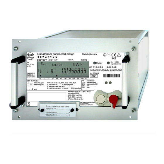
Page 8: Name Plate
Name plate 1 - Registered quadrants 2 - Type designation 3 - Voltage, current, frequency 4 - Safety and application information 5 - Conformity and certification marking 6 - Temperature class as per EN 60721-3-3 7 - Optical call sensor 8 - Test LED 9 - Accuracy class 10 - Type code... -
Page 9: Display
(optical or electrical) is communicating with the meter. The communication display flashes when parametrisation mode is active. On an XC-Rack with an LMN interface, this display lights up at irregular intervals as internal communications take place to provide the data for collection by an SMGW. - Page 10 4. The phase display indicates when individual phase voltages are applied. All 3 symbols flash on and off when the rotating field is wrong. 5. The unit shown matches the type of energy being measured or the measured value displayed. 6.
-
Page 11: Installation And Start-Up
Installation and start-up DANGER! Risk of fatal injury in case of contact with live parts! During installation or when replacing the meter, the wires connected to the meter must be de-energised. y Remove the corresponding pre-fuses, on the mains side and on the creation side in case of a two-sided feed. -
Page 12: Mounting And Connecting The Meter
ATTENTION! Application of excessive torque will damage the connection terminals! The appropriate torque is dependent on the type of connection line involved and its maximum current. y Tighten the connection terminals to the corresponding torque as per EN 60999-1. Mounting and connecting the meter The device may only be used in 19-inch racks in switch cabinets with a degree of protection of IP51 (or higher). -
Page 13: Transformer Connected Meter For Connection To Current And Voltage Transformers In Four-Conductor Systems
Transformer connected meter for connection to current and voltage transformers in four-conductor systems 4020 Transformer connected meter for connection to current and volt- age transformers in three-conductor systems (Aron circuit) The connections of the meter are on the back of the meter. -
Page 14: A) Meter With Essailec Connection System
Variants for meter connection DANGER! Danger to life due to excess voltages on the terminals of the current paths! The voltages on the terminals of the current paths must not be higher than the rated voltages of the voltage circuits and not be higher than 300 V towards N. - Page 15 With the Essailec connection system, the current paths are automatically short-circuited when the meter is pulled out of the plug-in unit frame. Therefore it is not necessary to short-circuit the current transformers beforehand. The contact assignment is variable and can be defined customer- specifically.
-
Page 16: B) Meter With Sub-D Connector
b) Meter with sub-D connector Communication Fibre optic interface LLS interface The Essailec contact assignment is variable and can be defined customer-specifically as shown in the previous example. The pin assignment of the sub-D connector is predetermined and cannot be modified: Contact Meaning GN D... - Page 17 The contact assignment is variable and can be defined customer- specifically. Example: Contact Meaning Contact Meaning Current phase 1 In Current phase 1 Out Current phase 2 In Current phase 2 Out Current phase 3 In Current phase 3 Out Voltage phase 1 Voltage phase 2 Voltage phase 3...
-
Page 18: Installation Control Tab C.86.0 (Optional)
Installation control tab C.86.0 (optional) Installation errors are saved in the installation control tab C.86.0. The tab is displayed as standard in the alternating display list on the display or output with the call list. Not assigned Wrong rotating field Phase failure Negative power direction Current interruption... -
Page 19: Error Tab F.f
Event Value Meaning Limiting current Limiting current exceeded L1 exceeded (I > Imax) Limiting current exceeded L2 Limiting current exceeded L3 Undervoltage Undervoltage L1 (U < 80%) Undervoltage L2 Undervoltage L3 Overvoltage Overvoltage L1 (U > 115%) Overvoltage L2 Overvoltage L3 Error tab F.F The meter has 32 error flags that are represented by an 8-digit HEX number. -
Page 20: Abbreviations
Abbreviations Active energy Positive active energy (customer obtains from utility company) Negative active energy (customer supplies to utility company) Accuracy class COSEM Companion Specification for Energy Metering Optical interface as per IEC 62056-21 DHCP Dynamic Host Configuration Protocol (dynamic assignment of IP addresses) Deutsches Institut für Normung e.V. - Page 21 Optical communication unit Overvoltage category Active power Positive active power (customer obtains from utility company) Negative active power (customer supplies to utility company) Protective Earth Physikalisch-Technische Bundesanstalt (National Metrology Institute of Germany) Reactive power Positive reactive power Negative reactive power Reactive energy Positive reactive energy Negative reactive energy...
-
Page 22: Eu Declaration Of Conformity
EU Declaration of Conformity The current EN Declaration of Conformity is available on the internet site www.emh-metering.com in the “Products” area for the meter’s product description.
Need help?
Do you have a question about the XC-RACK and is the answer not in the manual?
Questions and answers