Advertisement
Table of Contents
EMH metering
GmbH & Co. KG
Neu-Galliner Weg 1 • 19258 Gallin
GERMANY
Tel.
+49 38851 326-0
Fax
+49 38851 326-1129
Email info@emh-metering.com
Web
www.emh-metering.com
Tel.
+49 38851 326-1930 (Technical Support)
Email support@emh-metering.com
DIZ Generation G
Digital industrial meter
EN
Instructions for use
Scope of delivery .................................................................................... 2
Important information.............................................................................. 2
General description ................................................................................ 5
Technical data......................................................................................... 5
Housing, display and control elements ................................................... 7
Interfaces .............................................................................................. 12
Inputs and outputs ................................................................................ 14
Installation and start-up ........................................................................ 17
Meter operation .................................................................................... 26
Abbreviations ........................................................................................ 46
EU Declaration of Conformity ............................................................... 47
Issue date: 15 February 2022; subject to technical changes!
Specifications apply under reference conditions.
DIZ-G-EMH-BIA-E-1.60
Advertisement
Table of Contents

Subscribe to Our Youtube Channel
Related Manuals for EMH metering DIZ


Summary of Contents for EMH metering DIZ
-
Page 1: Table Of Contents
+49 38851 326-0 +49 38851 326-1129 Email info@emh-metering.com www.emh-metering.com Tel. +49 38851 326-1930 (Technical Support) Email support@emh-metering.com DIZ Generation G Digital industrial meter Instructions for use Scope of delivery ..................2 Important information................2 General description ................5 Technical data..................5 Housing, display and control elements ........... -
Page 2: Scope Of Delivery
Scope of delivery Please check that the contents of the packing box are complete before starting the installation and start-up procedure. y 1 Generation G DIZ device y 1 Instructions for use y Accessory (optional): • Path separator If the contents are incomplete or damaged, please contact your supplier. - Page 3 Maintenance and warranty instructions The device requires zero maintenance. It is not permitted to make any repairs in the event of any damage (e.g. due to transport or storage). If the device is opened, the warranty and the Declaration of Conformity will be rendered null and void.
- Page 4 Components Waste collection and disposal Battery Take safety precautions against short circuits before disposing of the batteries. Dispose of the batteries in their original packaging or insulate the terminals. Do not dispose of batteries with the domestic waste. Instead, observe the locally applicable waste and environmental protection standards.
-
Page 5: General Description
General description This generation G DIZ is a digital single-rate, two-rate or four-rate tariff meter for measuring positive and negative effective and reactive energy in 2, 3 and 4-wire networks. Tariff switching is performed via the internal real time clock (RTC) or an external control input. - Page 6 Control input Low voltage 5...40 V AC System voltage 58...230 V AC Output S0 output max. 27 V DC, 27 mA (passive) Opto-MOSFET max. 250 V AC/DC, 100 mA Power consumption per phase Voltage circuit < 2.0 VA / 1.0 W Current path <...
-
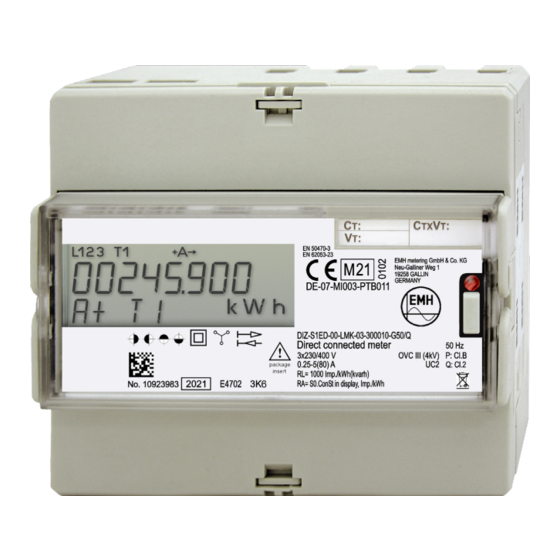
Page 7: Housing, Display And Control Elements
Housing, display and control elements 1 - Display 2 - Folding terminal cover 3 - Sealing eye 4 - Field for transformer plate (for transformer connected meters only) 5 - Test LED 6 - Call-up button for operating the meter 7 - Name plate 8 - Catch mechanism on the back of the meter... - Page 8 Name plate 1 - Space for ownership labelling 2 - Registered quadrants 3 - Safety and application information 4 - Product standards 5 - Conformity and certification marking 6 - Manufacturer’s address 7 - Frequency, accuracy classes 8 - Overvoltage category, utilisation category 9 - Type designation and type code 10 - Voltage, current 11 - Output pulse constant...
- Page 9 Display 1 - Phase indication 2 - Display of the active tariff 3 - Energy direction indicator 4 - Clock symbol 5 - Locking symbol (key) 6 - Communication symbol 7 - Test mode symbol (star) 8 - Display of units 9 - Value area 10 - Information area...
- Page 10 Phase indication L1, L2, L3 are Phase voltages are present permanently on: L1, L2, L3 flash: Rotating field of the voltage is wrong Display of the active tariff T1, T2, T3 or T4: Tariff 1, 2, 3 or 4 is active Energy direction indicator +A is permanently on: Meter has started and is registering positive...
- Page 11 Communication symbol Lit: Communication active via the electrical interface. Symbol frame flashes: Parametrisation status is activated. Test mode symbol (star) Permanently on: Test mode active. Pulse output of the active power on test LED with increased pulse value. Flashes: Test mode active. Output of the reactive pow- er on test LED with increased pulse value.
-
Page 12: Interfaces
Interfaces M-Bus interface The M-Bus interface is designed as per DIN EN 13757-2, -3. The M-Bus interface is galvanically isolated from the meter and is located on additional terminals 23 and 24. The following parameters can be transferred via the M-Bus: y Manufacturer identification y Medium y Primary and secondary address of the M-Bus... - Page 13 The data protocols used are the M-Bus protocol (see also M-Bus interface on page 12), SML (as per SML specification version 1.03) or Modbus-RTU® (Remote Terminal Unit). Properties Number of connected devices up to 32 Maximum cable length up to 1,000 m Data transfer rate 300...38400 baud, depending on the protocol...
-
Page 14: Inputs And Outputs
The settings for the serial interface are described as the transfer mode. The following options are available: y 1 start, 8 data, 1 stop bit, even parity (8E1) y 1 start, 8 data, 1 stop bit, uneven parity (8O1) y 1 start, 8 data, 2 stop bit, no parity (8N2) y 1 start, 8 data, 1 stop bit, no parity (8N1) The transfer mode can be changed via Modbus®... - Page 15 The pulse value can be set to 1, 10, 100 or 1 000 pulses/kWh or pulses/ kvarh. For a meter with a configured primary pulse output, the functionality of the pulse output also depends on the set total transformer factor. Choose the transformer factors so that a sufficiently large pulse pause is ensured when the meter is under maximum load.
- Page 16 The internal battery allows at least 250 readings with a duration of 1 min each to be performed. These readings can be performed over a period of 8 years; however, the service life of the battery can change due to the user profile.
-
Page 17: Installation And Start-Up
Installation and start-up Mounting the meter The meter can be mounted on TH 35-7.5 cap rails as per EN 60715. The following figures show the dimensions (in mm) relevant for mounting. The device may only be used in switch and meter cabinets with a degree of protection of IP51 (or higher). - Page 18 ATTENTION Damage to meter due to missing pre-fuse on control input! y Fuse-protect the control input with a pre-fuse of 0.5 A. All measurements in the following drawings are given in mm. Front view Left side view View from above View from below...
- Page 19 DANGER Risk of fatal injury due to arcing, fire and electric shock! The voltage taps in the meter are not fuse-protected, and are connect- ed directly to the main voltage. y External devices that are operated using the meter’s voltage taps must be fuse-protected with a pre-fuse of ≤...
- Page 20 2-wire version, connected directly 3-wire version, connected to current and voltage transformers 4-wire version, connected to current transformers The voltage variant 3x290/500V must not be used in 3-wire networks without N being connected.
- Page 21 4-wire version, connected directly 4-wire version, connected to current and voltage transformers 4-wire version, connected to current and voltage transformers (3 voltage transformers) (superposed circuit with 2 current trans- formers)
- Page 22 4-wire version, connected to current and voltage transformers (superposed circuit with 2 current transformers) Terminal blocks ATTENTION Application of excessive torque will damage the connection terminals! The appropriate torque is dependent on the type of connection line involved and its maximum current. y Tighten the connection terminals to the corresponding torque as per EN 60999-1.
- Page 23 DANGER Risk of fatal injury from high voltage when secondary circuits of power transformers are interrupted! In transformer connected meters, the high voltage generated on an interrupted secondary circuit of a power transformer can cause fatal injuries, and will destroy the power transformer. y Before disconnecting the current paths, short-circuit the secondary circuits of the power transformer at its testing terminals.
- Page 24 Dimensions, cross Current terminals / Voltage Auxiliary sections, torques N terminal terminals terminals up to up to 5 A up to 80 A/ 80 A up to 5 A Terminal dimensions 6.9 x 7.9 d = 3.1 d = 3.1 d = 2.5 W x H or d (mm) Minimum connection...
- Page 25 Terminal layout, top Terminal layout, bottom Interface 13/15 10/11 41/40/42 Connections valid for transformer Terminal number connected meter S0 outputs 41, 40, 42 Control input 13, 15 Neutral conductor N 10/11 Voltage input U1 Current input I1 Voltage input U2 Current input I2 Voltage input U3 Current input I3...
-
Page 26: Meter Operation
Meter operation Display control The following applies to operation by means of the call-up button: y K Pressing briefly (t < 2 s): • Moves to the next list value, menu item or setting value • Activates the illumination of the display if the meter is equipped in this way y L Pressing for a long time (2 s ≤... - Page 27 Standard operating display The standard operating display appears in normal operation. If the display is in a different state, the display automatically returns to the standard operating display 5 mins after the last time the button was pressed. The standard operating display shows the configuration-specific energy registers for the current tariff one by one at 5 s intervals (scrolling).
- Page 28 Menu item Display Button Display test Appears for 5 s Enter the call-up menu * If the meter has only 1 energy register, it is displayed for 10 s. Call-up menu The call-up menu is activated by pressing the call-up button in the standard operating display.
- Page 29 The following illustrations are provided to aid comprehension and can differ from the actual display on your meter. Menu item Display Button Tariff 1, Next menu item positive active energy Return to standard (if configured) operating display Tariff 2, Next menu item positive active energy Return to standard (if configured)
- Page 30 Further possible displays: y Voltage transformer constant (U-Const) y Current (I) y Current transformer constant (I-Const) y Current on L1 (I1) y Active power (P) y Current on L2 (I2) y Total active power (P y Current on L3 (I3) total y Active power on L1 (P1) y S0 pulse constant...
- Page 31 Menu item Display Button Go to start of menu or Go to start of menu to call-up menu Return to call-up menu Tariff list (“TARIFLST”) The tariff list contains all energy registers. The following energy registers and amount of tariffs are possible: Meter type Power Energy...
- Page 32 Menu item Display Button Tariff 4, positive active energy Next menu item (if configured) Tariff-free, negative active energy Next menu item Tariff 1, negative active energy Next menu item (if configured) Tariff 2, negative active energy Next menu item (if configured) Tariff 3, negative active energy Next menu item...
- Page 33 Menu item Display Button Go to start of menu or Go to start of menu to call-up menu Return to call-up menu Measurements list (“METERLST”) The measurements list contains the recorded instantaneous values and represents the measuring instrument function of the meter. If transformer factors have been set, they are included in the instanta- neous values and represent the primary-side values.
- Page 34 Menu item Display Button Voltage L3-L1 (only for 3- or Next menu item 4-wire meters) Current L1 (only for 2-wire meters) Next menu item Current L1 (only for 3- or Next menu item 4-wire meters) Current L2 (only for 4-wire meters) Next menu item Current L3 (only for 3- or...
- Page 35 Menu item Display Button Total reactive power Next menu item Reactive power L1 (only for 4-wire meters) Next menu item Reactive power L2 (only for 4-wire meters) Next menu item Reactive power L3 (only for 4-wire meters) Next menu item Apparent power (only for 2-wire meters) Next menu item...
- Page 36 Menu item Display Button Power factor L3 (only for 4-wire meters) Next menu item Frequency Next menu item Go to start of menu or Go to start of menu to call-up menu Return to call-up menu Device settings (“SETLIST”) The settings of the meter can be viewed in the device settings list. Some of the settings can be changed in the editing menu as long as it is available and not locked.
- Page 37 Menu item Display Button Recording direction of energies Next menu item Electrical interface (possible displays: MbuS Next menu item SER, Modb SER (for Modbus), SML SER or Lon, if configured) Pulse constant S0 outputs Next menu item in pulses/kWh Pulse length S0 outputs Next menu item in milliseconds...
- Page 38 Editing menu (“Edit”) The state of the editing menu is indicated on the display by the locking symbol (see description of the display on page 9). As long as the editing menu is unlocked, the meter must not be used for billing! Modifiable parameters If the editing menu is not locked (flashing key symbol on the display), the following parameters can be changed:...
- Page 39 b) Arities of the energy registers: The register resolution can be modified via the display control or the data interface. Possible values: y Direct metering meters: • 8.0 (default value), 7.1, 6.2, 5.3 y Transformer connected meters: • Secondary meters: 8.0, 7.1, 6.2, 5.3 (default value), 4.4 •...
- Page 40 Possible register resolutions for a primary meter with 3 x 230/400 V: Transformer factor Register resolution Unit (VT x CT) 1 - 5 8.0, 7.1, 6.2, 5.3 kWh/kvarh 6 - 59 8.0, 7.1, 6.2 kWh/kvarh 60 - 599 8.0, 7.1 kWh/kvarh 600 - 999 kWh/kvarh...
- Page 41 Display Button Menu item U transformer factor Next menu item Edit value I transformer factor Next menu item Edit value Edit the first digit Count digit up by 1 (digit flashes) Edit next digit Count digit up by 1 Edit the second digit (digit flashes) Edit next digit Count digit up by 1...
- Page 42 Check the transformer factors: Menu item Display Button Transformer factor Overwrite the transformer too large: factors VT x CT > 999999 Enter new transformer factors, set values are rejected Total transformer No display Adopt the values, default factor okay: value for register resolution is VT x CT ≤...
- Page 43 Menu item Display Button Finally lock and exit Return to previous menu editing mode (LocK. item Edit flashes) Exit and irrevocably lock editing mode, go to call-up menu and adopt all values Press the call-up button for a long time irrevocably locks the editing mode, i.e.
- Page 44 Set menu – example: The value for the primary address is changed from 001 to 002. The same procedure applies when changing other values. Menu item Display Button Activate the set menu Next menu item Enter the set menu Next menu item Set the date (format: dd.mm.yyyy) Edit value...
- Page 45 Menu item Display Button Secondary address Next menu item (adjustable from Edit value 00000000-99999999; only for meters with M-Bus) Next menu item Baud rate of M-Bus (can be set to 0300, Edit value 2400 and 9600 bd; only for meters with M-Bus) Address of Modbus®...
-
Page 46: Abbreviations
Abbreviations Active energy Positive active energy (customer obtains from utility company) −A Negative active energy (customer supplies to utility company) Deutsches Institut für Normung e.V. (German Standardisation Institute) European Norm Utility company Unit of division according to DIN 43880 Current Identification Ingress Protection International Standard Organisation... -
Page 47: Eu Declaration Of Conformity
EU Declaration of Conformity The current EU Declaration of Conformity is available on the in- ternet site www.emh-metering.com in the “Products & Solutions” area for the meter’s product description. The specifications for creating the Declaration of Conformity can change at any time, so save the Declaration of Conformity when the device is delivered.
Need help?
Do you have a question about the DIZ and is the answer not in the manual?
Questions and answers