Table of Contents
Advertisement
Quick Links
Advertisement
Table of Contents

Related Manuals for Supermicro S5


Summary of Contents for Supermicro S5
- Page 1 S5 C hASSiS SCGS50-000R, SCGS5B-000R, SCGS5A-753R USER’S MANUAL Revision 1.0c...
- Page 2 This product, including software and documentation, is the property of Supermicro and/or its licensors, and is supplied only under a license. Any use or reproduction of this product is not allowed, except as expressly permitted by the terms of said license.
- Page 3 Preface Preface About this Manual This manual is written for professional system integrators and PC technicians. It provides information for the installation and use of the chassis. Installation and maintenance should be performed by experienced technicians only. This document lists compatible parts available when this document was published. Refer to the Supermicor web site for updates on supported parts and configurations.
-
Page 4: Table Of Contents
SCGS5 User's Manual Contents Contacting Supermicro ....................6 Chapter 1 Introduction ................1-1 Overview ......................1-1 Key Features ....................1-1 Components ....................1-2 Drives ......................1-2 Fans and Cooling .................... 1-2 Motherboard ....................1-2 Expansion Slots ....................1-2 External I/O Connections ................1-2 User Interface .................... - Page 5 Preface Installing the Motherboard ................3-10 Installing the I/O Shield ................3-10 Motherboard Standoffs ...................3-11 Motherboard Installation .................3-11 Fans and Cooling ..................3-13 Water Cooled Heat Sink ................3-14 Air Flow ......................3-15 Dust Filters ....................3-15 Installing Expansion Cards ................3-16 Power Supply ....................
-
Page 6: Contacting Supermicro
Super Micro Computer, Inc. 980 Rock Ave. San Jose, CA 95131 U.S.A. Tel: +1 (408) 503-8000 Fax: +1 (408) 503-8008 Email: marketing@supermicro.com (General Information) support@supermicro.com (Technical Support) Web Site: www.supermicro.com Europe Address: Super Micro Computer B.V. Het Sterrenbeeld 28, 5215 ML... -
Page 7: Chapter 1 Introduction
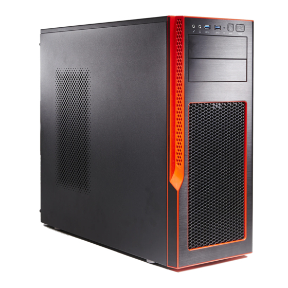
Chapter 1 Introduction Chapter 1 Introduction Overview Supermicro's S5 gaming chassis (SCGS5) offers extreme storage and cooling opportunities in a sleek, attractive form. It can house a powerful ATX form factor motherboard supporting outstanding gaming-level high performance. Key Features •... -
Page 8: Components
SCGS5 Chassis Manual Components The primary components are described below. Drives The standard configuration includes two 5.25" drive bays, four 2.5" drive bays, and six combination bays that can house either 3.5" or 2.5" drives. • Each 5.25" bay can be configured to accept a 3.5"drive, or one or two 2.5" drives. •... -
Page 9: Where To Get Replacement Components
For faster service, RMA authorizations may be requested online (http://www. supermicro.com/support/rma/). Whenever possible, repack the chassis in the original Supermicro carton, using the original packaging material. If these are no longer available, be sure to pack the chassis securely, using packaging material to surround the chassis so that it does not shift within the carton and become damaged during shipping. - Page 10 SCGS5 Chassis Manual Notes...
-
Page 11: Chapter 2 Standardized Warning Statements For Ac Systems
Only certified technicians should attempt to install or configure components. Read this appendix in its entirety before installing or configuring components in the Supermicro chassis. These warnings may also be found on our web site at http://www.supermicro.com/ about/policies/safety_information.cfm. Warning Definition Warning! This warning symbol means danger. - Page 12 SCGS5 Chassis Manual Warnung WICHTIGE SICHERHEITSHINWEISE Dieses Warnsymbol bedeutet Gefahr. Sie befinden sich in einer Situation, die zu Verletzungen führen kann. Machen Sie sich vor der Arbeit mit Geräten mit den Gefahren elektrischer Schaltungen und den üblichen Verfahren zur Vorbeugung vor Unfällen vertraut.
- Page 13 Chapter 2: Warning Statements for AC Systems جسذٌة اصابة ًتتسبب ف حالة ٌوكي أى ًاًك ف خطز ًٌٌع هذا الزهز !تحذٌز الذوائز بالوخاطز الٌاجوة عي ي على علن ، ك هعذات تعول على أي قبل أى الكهزبائٍة حىادث أي وقىع وٌع...
-
Page 14: Installation Instructions
SCGS5 Chassis Manual Installation Instructions Warning! Read the installation instructions before connecting the system to the power source. 設置手順書 システムを電源に接続する前に、 設置手順書をお読み下さい。 警告 将此系统连接电源前,请先阅读安装说明。 警告 將系統與電源連接前,請先閱讀安裝說明。 Warnung Vor dem Anschließen des Systems an die Stromquelle die Installationsanweisungen lesen. ¡Advertencia! Lea las instrucciones de instalación antes de conectar el sistema a la red de alimentación. -
Page 15: Circuit Breaker
Chapter 2: Warning Statements for AC Systems Circuit Breaker Warning! This product relies on the building's installation for short-circuit (overcurrent) protection. Ensure that the protective device is rated not greater than: 250 V, 20 A. サーキッ ト ・ ブレーカー この製品は、 短絡 (過電流) 保護装置がある建物での設置を前提としています。 保護装置の定格が250 V、... -
Page 16: Power Disconnection Warning
SCGS5 Chassis Manual 경고! 이 제품은 전원의 단락(과전류)방지에 대해서 전적으로 건물의 관련 설비에 의존합니다. 보호장치의 정격이 반드시 250V(볼트), 20A(암페어)를 초과하지 않도록 해야 합니다. Waarschuwing Dit product is afhankelijk van de kortsluitbeveiliging (overspanning) van uw electrische installatie. Controleer of het beveiligde aparaat niet groter gedimensioneerd is dan 220V, 20A. - Page 17 Chapter 2: Warning Statements for AC Systems ¡Advertencia! El sistema debe ser disconnected de todas las fuentes de energía y del cable eléctrico quitado de los módulos de fuente de alimentación antes de tener acceso el interior del chasis para instalar o para quitar componentes de sistema. Attention Le système doit être débranché...
-
Page 18: Equipment Installation
SCGS5 Chassis Manual Equipment Installation Warning! Only trained and qualified personnel should be allowed to install, replace, or service this equipment. 機器の設置 トレーニングを受け認定された人だけがこの装置の設置、 交換、 またはサービスを許可 されています。 警告 只有经过培训且具有资格的人员才能进行此设备的安装、更换和维修。 警告 只有經過受訓且具資格人員才可安裝、更換與維修此設備。 Warnung Das Installieren, Ersetzen oder Bedienen dieser Ausrüstung sollte nur geschultem, qualifiziertem Personal gestattet werden. -
Page 19: Restricted Area
Chapter 2: Warning Statements for AC Systems Waarschuwing Deze apparatuur mag alleen worden geïnstalleerd, vervangen of hersteld door geschoold en gekwalificeerd personeel. Restricted Area Warning! This unit is intended for installation in restricted access areas. A restricted access area can be accessed only through the use of a special tool, lock and key, or other means of security. -
Page 20: Battery Handling
SCGS5 Chassis Manual אזור עם גישה מוגבלת !אזהרה יש להתקין את היחידה באזורים שיש בהם הגבלת גישה. הגישה ניתנת בעזרת .)'כלי אבטחה בלבד (מפתח, מנעול וכד محظورة مناطق ٍنتركُبها ف هذه انىحذة تخصيص تم ،أداة خاصت من خالل استخذاو فقط محظورة... - Page 21 Chapter 2: Warning Statements for AC Systems Warnung Bei Einsetzen einer falschen Batterie besteht Explosionsgefahr. Ersetzen Sie die Batterie nur durch den gleichen oder vom Hersteller empfohlenen Batterietyp. Entsorgen Sie die benutzten Batterien nach den Anweisungen des Herstellers. Attention Danger d'explosion si la pile n'est pas remplacée correctement. Ne la remplacer que par une pile de type semblable ou équivalent, recommandée par le fabricant.
-
Page 22: Redundant Power Supplies
SCGS5 Chassis Manual Redundant Power Supplies Note: Not applicable to this chassis. Warning! This unit might have more than one power supply connection. All connections must be removed to de-energize the unit. 冗長電源装置 このユニッ トは複数の電源装置が接続されている場合があります。 ユニッ トの電源を切るためには、 すべての接続を取り外さなければなりません。 警告 此部件连接的电源可能不止一个,必须将所有电源断开才能停止给该部件供电。 警告... -
Page 23: Backplane Voltage
Chapter 2: Warning Statements for AC Systems امداد الطاقة بوحدات عدة اتصاالت جهاز ال يكون لهذا قد الكهرباء عن وحدة ال لعسل كافة االتصاالت يجب إزالة 경고! 이 장치에는 한 개 이상의 전원 공급 단자가 연결되어 있을 수 있습니다. 이 장치에 전원을... -
Page 24: Comply With Local And National Electrical Codes
SCGS5 Chassis Manual מתח בפנל האחורי !הרה אז קיימת סכנת מתח בפנל האחורי בזמן תפעול המערכת. יש להיזהר במהלך .העבודה اللىحة أوالطاقة المىجىدة على التيار الكهزبائي مه خطز هناك هذا الجهاس خدمة كه حذرا عند يعمل النظام عندما يكىن 경고! 시스템이... -
Page 25: Product Disposal
Chapter 2: Warning Statements for AC Systems Attention L'équipement doit être installé conformément aux normes électriques nationales et locales. תיאום חוקי החשמל הארצי !אזהרה הציוד חייבת להיות תואמת לחוקי החשמל המקומיים והארציים התקנת المتعلقة المحلية والىطىية قىاويه يجب أن يمتثل لل الكهربائية... -
Page 26: Hot Swap Fan Warning
SCGS5 Chassis Manual ¡Advertencia! Al deshacerse por completo de este producto debe seguir todas las leyes y reglamentos nacionales. Attention La mise au rebut ou le recyclage de ce produit sont généralement soumis à des lois et/ou directives de respect de l'environnement. Renseignez-vous auprès de l'organisme compétent. - Page 27 Chapter 2: Warning Statements for AC Systems 警告 當您從機架移除風扇裝置,風扇可能仍在轉動。小心不要將手指、螺絲起子和其他 物品太靠近風扇。 Warnung Die Lüfter drehen sich u. U. noch, wenn die Lüfterbaugruppe aus dem Chassis genommen wird. Halten Sie Finger, Schraubendreher und andere Gegenstände von den Öffnungen des Lüftergehäuses entfernt. ¡Advertencia! Los ventiladores podran dar vuelta cuando usted quite ell montaje del ventilador del chasis.
-
Page 28: Power Cable And Ac Adapter
Electrical Appliance and Material Safety Law prohibits the use of UL or CSA -certified cables (that have UL/CSA shown on the code) for any other electrical devices than products designated by Supermicro only. 電源コードとACアダプター 製品を設置する場合、 提供または指定された接続ケーブル、 電源コードとACアダプター... - Page 29 Appareils électroménagers et de loi sur la sécurité Matériel interdit l'utilisation de UL ou CSA câbles certifiés qui ont UL ou CSA indiqué sur le code pour tous les autres appareils électriques que les produits désignés par Supermicro seulement.
- Page 30 SCGS5 Chassis Manual Notes 2-20...
-
Page 31: Chapter 3 Chassis Setup And Maintenance
Chapter 3: Chassis Setup and Maintenance Chapter 3 Chassis Setup and Maintenance Overview This chapter covers the steps required to install components and perform maintenance on the chassis. Most tasks can be accomplished without tools. Review the warnings and precautions listed in the manual before setting up or servicing this chassis. -
Page 32: Removing Power From The System
S5 Chassis Manual Removing Power from the System Before performing most setup or maintenance tasks, use the following procedure to ensure that power has been removed from the system. 1. Use the operating system to power down the system, following the on-screen prompts. -
Page 33: Removing The Chassis Covers
Chapter 3: Chassis Setup and Maintenance Removing the Chassis Covers Caution: Except for short periods of time, do not operate the system without the cover in place. The chassis cover must be in place to allow proper airflow and prevent overheating. Left Side and Right Side Covers Removing a Side Chassis Cover 1. -
Page 34: Front Bezel
S5 Chassis Manual Front Bezel Remove the front bezel by pulling it off from the bottom of the bezel. This should only be necessary when replacing the front fans. Figure 3-3. Removing the Front Bezel... -
Page 35: Installing Drives
Chapter 3: Chassis Setup and Maintenance Installing Drives The standard configuration includes two 5.25" drive bays, four 2.5" drive bays, and six combination bays that can house either 3.5" or 2.5" drives. • Each 5.25" bay can be configured to accept a removable media drive, such as DVD, or a storage device, such as a 3.5"... - Page 36 S5 Chassis Manual Installing a DVD Drive in the 5.25" Drive Bay Replace a drive tray with a DVD drive. 1. Open the chassis left side cover. 2. Locate and press the release tab for the drive tray where you want to place the DVD drive.
- Page 37 Chapter 3: Chassis Setup and Maintenance Installing a Storage Device in the 5.25" Drive Tray You can install a 3.5" drive, one or two 2.5" disk drives or solid state drives. 1. Open the chassis left side cover. 2. Locate and press the release tab (Figure 3-5) for the drive tray in which you want to place the drive.
- Page 38 S5 Chassis Manual Installing Disk Drives into the Cage You can install up to four 2.5" drives into the dedicated center cage. You can also install three drives into each of the upper and lower combination cages. 1. Open the chassis left side cover.
- Page 39 Chapter 3: Chassis Setup and Maintenance Figure 3-8. Mounting Tray for 3.5" Drive Figure 3-9. Mounting Tray for 2.5" Drive 3. Secure the drive into the mounting bracket. • For 2.5" drives in the dedicated bays (center cage), flex the drive bracket and drop the drive in with the connector side facing into the chassis.
-
Page 40: Installing The Motherboard
S5 Chassis Manual Installing the Motherboard Installing the I/O Shield The shield encloses the I/O ports at the rear of the chassis. Install it before installing the motherboard. The motherboard package should include a compatible shield. Installing the I/O Shield 1. -
Page 41: Motherboard Standoffs
Chapter 3: Chassis Setup and Maintenance Motherboard Standoffs Standoffs prevent short circuits by securing space between the motherboard and the chassis surface. Three standoffs are pre-installed. Some motherboards require additional standoffs. The chassis accessory box contains standoffs and rounded Phillips head screws. Compare the mounting holes in the motherboard to those in the chassis and add or remove standoffs as needed. - Page 42 S5 Chassis Manual 3. Lay the motherboard on the chassis, aligning the standoffs. 4. Secure the motherboard to the standoffs using the rounded, Phillips head screws. Do not exceed eight inch-pounds of torque when tightening the screws. 5. Secure the CPU, heatsinks, and other components to the motherboard as described in the motherboard documentation.
-
Page 43: Fans And Cooling
Chapter 3: Chassis Setup and Maintenance Fans and Cooling The chassis includes two 120mm PWM fans in the front and one 120mm PWM in the rear. Other fan mounts and configurations are possible. • Two front fans can be upgraded to 140mm. •... - Page 44 S5 Chassis Manual Figure 3-13. All Possible Fan Placements (This diagram illustrates fan positions; actual fans include finger guards.) 3-14...
-
Page 45: Air Flow
Chapter 3: Chassis Setup and Maintenance Air Flow Make sure cables do not obstruct the cooling airflow. Dust Filters The chassis features a dust filter in front of the front fans, and two magnetic dust filters, one on top of the chassis and one on the bottom. They can be lifted off and cleaned to improve system air flow circulation. -
Page 46: Installing Expansion Cards
5. Replace the chassis side cover and power up the system. Power Supply The SC-GS5A-753R model comes with a 750W power supply. Other S5 chassis do not include a power supply, but accomodate any standard PS2 size power supply. Mount it on the rear floor of the chassis. The power supply fan may be on top or under the power supply.
Need help?
Do you have a question about the S5 and is the answer not in the manual?
Questions and answers