Advertisement
Quick Links
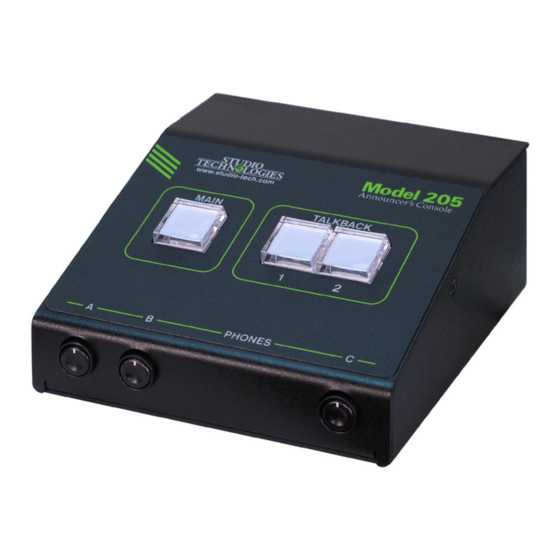
Model 205 Announcer's Console
User Guide
Issue 3, August 2020
This User Guide is applicable for serial numbers
M205-00501 and later with application firmware 1.4 and later
and STcontroller application version 2.04.00 and later.
Copyright © 2020 by Studio Technologies, Inc., all rights reserved
www.studio-tech.com
50641-0820, Issue 3
Advertisement

Subscribe to Our Youtube Channel
Related Manuals for Studio Technologies 205


Summary of Contents for Studio Technologies 205
- Page 1 Issue 3, August 2020 This User Guide is applicable for serial numbers M205-00501 and later with application firmware 1.4 and later and STcontroller application version 2.04.00 and later. Copyright © 2020 by Studio Technologies, Inc., all rights reserved www.studio-tech.com 50641-0820, Issue 3...
- Page 2 This page intentionally left blank.
-
Page 3: Table Of Contents
Revision History ............4 Introduction ..............5 Getting Started ............. 10 Operation ..............19 Technical Notes ............24 Specifications ............... 28 Appendix A: Model 205 Block Diagram ......29 Model 205 User Guide Issue 3, August 2020 Studio Technologies, Inc. Page 3... -
Page 4: Revision History
M205-00501 and later.) Issue 2, October 2018: • Documents addition of the Push to Mute/Tap to Latch main button operating mode. Issue 1, April 2018: • Initial release. Issue 3, August 2020 Model 205 User Guide Page 4 Studio Technologies, Inc. -
Page 5: Introduction
Applications and streaming broadcast applications. The unit is housed in a compact, rugged steel The Model 205 on its own can provide an enclosure that’s intended for table-top “all-Dante” solution for one on-air talent use. Calling the Model 205 “cute” or “cool”... - Page 6 I/O unit. Supporting these scenarios is a monaural earpiece can be connected to not a problem as the Model 205 supplies a the phones output jack. microphone output connection that’s specifi- External switches or contact closures can cally intended for this purpose.
- Page 7 Ethernet Data and PoE AES67 interoperability standard. In this mode the three transmitter (output) chan- The Model 205 connects to a local area net- nels will function in multicast; unicast is not work (LAN) by way of a standard 100 Mb/s supported.
- Page 8 Configuration Flexibility main or talkback pushbutton switches. In The Model 205 can be configured to meet this way, activation of a remote control input the needs of specific applications and user will emulate a user pressing its associated preferences.
- Page 9 Model the unit by way of Dante inputs 3 and 4. 205 by way of Dante inputs 1 and 2 and is routed in stereo to the left and right The integrated sidetone function can be channels of the headphone output.
-
Page 10: Getting Started
Firmware Updating using a cable terminated with a standard The Model 205 was designed so that its 3-pin female XLR connector. Special ap- capabilities and performance can be en- plications may utilize the two remote control hanced in the future. - Page 11 (“dual-muff”) broadcast-style headsets can Microphone Input be directly connected using a 3-conductor The Model 205 provides a 3-pin female XLR ¼-inch plug. Following the usual convention connector that allows a balanced dynamic or the left channel should be terminated on the...
- Page 12 3-conductor jack is located on the Model microphone output circuitry. 205’s back panel and provides access to the two remote control inputs. The input The microphone output can be connected circuitry is “active low,” with 3.4 k ohm resis- to balanced (differential) analog micro- tors connected to +3.3 volts DC to act as...
- Page 13 OS X® operating systems. The Model 205 appropriate. While technically the Model uses the Ultimo 4-input/4-output integrated 205 can serve as a clock master for a Dante circuit to implement the Dante functionality. network (as can all Dante-enabled devices) The Model 205 can also be configured to...
- Page 14 35, 43, 52, and 59 dB. The compressor active LED, orange in color Installing STcontroller and visible on the back of the Model 205’s STcontroller is available free of charge on enclosure adjacent to the microphone input the Studio Technologies’ website (www.
- Page 15 B adjusts its level. A stereo pair can have a single potentiometer to simultane- enter the Model 205 by way of Dante input ously adjust the level of a stereo pair while channels 3 and 4. These signals, whose...
- Page 16 Its level will be adjusted using pot signal to fully mute. Selecting the full mute B. A stereo pair can enter the Model 205 by mode may be appropriate for applications way of Dante input channels 3 and 4. These where minimizing the chance of audio “leak-...
- Page 17 • Push to Mute: If this mode is selected either from inactive-to-active or from ac- the main button function will normally be tive-to-inactive. Upon Model 205 power active and its green LED lit. The audio up the main button will be in its inactive signal associated with the microphone in- state and its red LED will be lit.
- Page 18 Specifically, it determines how the Dante until the main button is released. Upon main output channel and the microphone Model 205 power up the main button will output connector operate vis-à-vis the talk- be in its inactive state and its red LED will back functions.
-
Page 19: Operation
Some applications may utilize either mode is not appropriate when headphones or both of the remote control inputs. Remote are going to be connected to the Model 205! Control Input 1 can provide a low-voltage Remote Control Inputs DC tally output that is active whenever the main output function is active. - Page 20 (timing reference) is being received. It will slowly flash green when this specific Model Functions within the Dante Controller and 205 is part of a Dante network and is serv- STcontroller software applications allow ing as the clock master. It’s possible that a specific Model 205 unit to be identified.
- Page 21 ANNOUNCER’S CONSOLE Compressor Active LED and and the microphone output connector that’s located on the back panel of the Model 205. Mic Preamp Gain How the button functions will depend on the An LED indicator, orange in color, is located...
- Page 22 Upon Model pressed and held. 205 power up the audio signal will be in • Latching: If this mode is selected the audio its muted state. signal associated with a Dante talkback •...
- Page 23 (reduced in level or attenuated) is used to select the overall operating mode by 18 dB whenever one of the main or of the Model 205. Specifically, the system talkback functions are active. In this way, operating mode determines how the main the headphone output can be connected function will operate vis-à-vis the talkback...
-
Page 24: Technical Notes
Ultimo integrated circuits Users should find the headphone audio to implement Dante. The Model 205 uses quality to be excellent, with high maximum Ultimo and, as such, a direct one-to-one output level and low distortion. Analog au-... - Page 25 Connect applications. Refer to the Audinate website the Model 205 unit to the network and let (www.audinate.com) for details on optimiz- it connect and start to function. Then, after ing networks for Dante applications.
- Page 26 Power-over-Ethernet (PoE) to the naming convention required by the Ethernet source. Model 205, the name of the zip file itself will 5. After a few seconds the Model 205 will include the file’s version number. For exam- run a “boot loader”...
- Page 27 Factory Defaults feature. Then click on the applied to the Model 205. Upon power up OK box. The values shown on the screen the main button’s LED will flash on and off should reflect the default values.
-
Page 28: Specifications
Remote Control Inputs: 3-conductor 3.5 mm jack of gain Ethernet: Neutrik etherCON RJ45 Dynamic Range: 98 dB, A-weighted USB: type A receptacle (located inside Model 205’s Phantom Power: P48 per IEC 61938 standard, on/off enclosure and used only for updating firmware) selectable with status LED Configuration: requires Studio Technologies’... -
Page 29: Appendix A: Model 205 Block Diagram
MODEL 205 ANNOUNCER’S CONSOLE Appendix A: Model 205 Block Diagram The following block diagram shows a simplified version of the Model 205’s microphone input and microphone output circuitry. Model 205 User Guide Issue 3, August 2020 Studio Technologies, Inc. Page 29...
Need help?
Do you have a question about the 205 and is the answer not in the manual?
Questions and answers