Advertisement
Available languages
Available languages
Quick Links
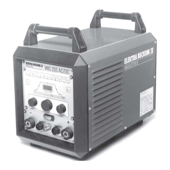
Betriebsanleitung WIG 255 AC/DC
Operating Instructions TIG 255 AC/DC
Instructions d'utilisation TIG 255 AC/DC
Achtung!
Bitte lesen Sie die Betriebsanleitung vor der Installation und Inbetriebnahme des
WIG 255 AC/DC Schweißgerätes aufmerksam durch.
Note
Read these instructions carefully before commissioning and operating this TIG Welding Machine
Attention !
Veuillez lire attentivement les instructions d'utilisation avant de mettre en service
l'appareil de soudage TIG 255 AC/DC.
Technische Änderungen vorbehalten!
Elektra Beckum reserves the right to change specifications and design without prior notice and without incurring
obligation of any kind. Equipment referred to as available or optional may be at extra cost.
48/02 - de, en, fr - 2.0
Sous réserve de modifications techniques !
Art.-Nr. 115 118 9942
Advertisement

Related Manuals for Elektra Beckum TIG 255 AC/DC


Summary of Contents for Elektra Beckum TIG 255 AC/DC
- Page 1 TIG 255 AC/DC. Technische Änderungen vorbehalten! Elektra Beckum reserves the right to change specifications and design without prior notice and without incurring obligation of any kind. Equipment referred to as available or optional may be at extra cost.
- Page 2 Inhalt: Technische Daten Gebrauchshinweise Anwendungsbereiche Überlastung/Netzfehler Inbetriebnahme Gefahrenhinweise Funktionsbeschreibung Störungsbeseitigung Stromlaufplan 1.0 Technische Daten Netzspannung 3~400 V Netzfrequenz 50-60 Hz Leerlaufspannung 57 V Stromeinstellbereich 5-250 A AC/DC, Elektrode Eingangsleistung 6,6 KVA WIG AC/DC, 9,9 KVA Elektrode Arbeitsspannung 10,2-20 V WIG AC/DC 20,2-30 V Elektrode Eingangs-Höchststrom 16 A...
- Page 3 Produkthaftung/Garantie: Nicht aufgeführte Arbeiten und Einsatzmöglichkeiten bedürfen der schriftlichen Genehmigung der Firma Elektra Beckum AG , Postfach 1352, D-49703 Meppen. Jeder Maschine und dem Maschinenzubehör ist eine Garantiekarte beigefügt. Zur Wahrung Ihres Garantieanspruches und im Interesse der Produktsicherheit achten Sie bitte darauf, daß die Garantiekarte sofort beim Verkauf ausgefüllt und die Antwortkarte ans Werk geschickt wird.
- Page 4 4.1 Bedienungselemente Netzschalter EIN/AUS Anschluß: 1. Bei WIG-Betrieb: Massezange 2. Bei Elektrodenhandschweißen: (+) Pol Anschluß für Hand- oder Fußfernregler Anschluß für Schutzgas Anschluß für Brennerschaltung Anschluß: 1. Bei WIG-Betrieb: Brenneranschluß 2. Bei Elektrodenhandschweißen: (-) Pol Drehpotentiometer für Funktionswahl Drehpotentiometer für Werteinstellung Drehpotentiometer für die Lichtbogeneinstellung Bei der Funktion WIG-AC Schweißen - Einstellung der Balance für die Ausregelung des Gleichrichtereffektes Digitalanzeige...
- Page 5 4.2 Funktionsbeschreibung Elektrodenhandschweißen - Gerät wir am Netzschalter (1) eingeschaltet. - Drehpotentiometer "Funktion" Drehung nach links bis LED-Grün des Gruppen- bildes "Schweißarten-Anzeige" (13) leuchtet. Drehpotentiometer "Wert" Dre- hung auf Elektrodenfunktion, LED-Rot leuchtet und zeigt die Aktivierung an. - Drehpotentiometer "Funktion" Drehung nach links bis LED-Grün des Funktions- bildes "Hotstart"...
- Page 6 Wenn für das WIG-DC-Schweißen zusätzlich die Pulsfunktion aktiviert werden soll, folgender Ablauf (Beschreibung des Pulsschweißen 4.3.8): - Drehpotentiometer "Funktion" Drehung nach rechts bis LED-Grün des Bildes "Pulsen" (15) erleuchtet. Dreh- potentiometer "Wert" Drehung, LED-Rot erleuchtet und die Pulsfunktion ist aktiviert. - Drehpotentiometer "Funktion"...
- Page 7 4.3.3 Anschluß Das Hauptstromkabel des WIG-Brenners wird an (6) und die Steuerung des WIG-Brenners an (5) angeschlos- sen. Die Gaszufuhr erfolgt über die Schnellkupplung (4). Die Verbindung zum Schweißtisch bzw. Werkstück erfolgt mit dem Anschluß (2). Zusätzlich kann über den Anschluß (3) ein Hand- oder Fußfernregler angeschlos- sen werden.
- Page 8 4.3.6 4-Takt Betrieb Bei der Betätigung des Brennertasters Rot (Bild 1: 20) wird der Schweißvorgang gestartet (Zündung durch HF- oder Kontaktzündung). Solange der Brennertaster (Bild 1: 20) gedrückt wird, brennt der LB mit seinem Startstrom. Der Startstrom kann wie bei 2-Takt Betrieb eingestellt werden, mindestens jedoch 5 A (Suchlichtbogen). Nach dem Loslassen des Brennertasters Rot Bild (1: 20) läuft der Lichtbogen-Strom durch Einstellung der Anstiegszeit (10) von 0,1 - 10s auf den eingestellten Schweißstrom.
- Page 9 4.3.8 Impulsschweißen Beim Pulsschweißen brennt ein Lichtbogen mit stufenlos einstellbarem Grundstrom (Funktion 16 von 5 - 250 A). Der Pulsstrom wird über die Funktion 16 eingestellt. Pulszeit (17) und Pulspause (18) sind stufenlos von 0,1 - 5 s einstellbar. Pulsdauer - Pulse time Stromanstieg Up-slope Brennerschalter...
- Page 10 5.3 Anschliff Das Anschleifen der Elektroden darf bei Gleichstrom nur in Längsrichtung erfolgen und bei Wechselstrom Elektroden- durchmesser 1,6 mm überhaupt nicht anschleifen und bei D >1,6 mm spitzwinklig und mit gebrochener Spitze. Beim Schweißen mit Wechselstrom bildet sich automatisch an der Elektrode eine Tropfenform (Kalotte) heraus. Schweißen mit Gleichstrom Die Elektrode wird in der Regel durch ~30°...
- Page 11 Aluminium Wechselstrom; Minuspol an der Elektrode; Schweißposition w; Stumpfnaht Blechdicke Fugenform Lagenzahl Durchmesser Stromstärke Elektrode Schweißstab 1,6 oder 2,4 40 ... 50 1,6 oder 2,4 60 ... 80 110 ... 130 1 oder 2 2,4 oder 3,2 120 ... 150 1 oder 2 150 ...
- Page 12 8.0 Störungsbeseitigung Gerät zündet nicht im WIG-Betrieb Ursache: Brenner defekt Masse defekt oder schlecht angeschlossen Wolfram-Elektrode verschmutzt Gerät arbeitet nur im Minimalstrom Ursache: Potentiometer im Brennerhandgriff oder Fußregler defekt. Gerät zündet schlecht Ursache: - kein Gas (oder nicht genügend Gas) - Wolframelektroden falsch angeschliffern - falscher Elektrodendurchmesser - Wolframelektroden durch Oxyde oder Verunreinigung belegt (schlechte Zümdeigenschaften)
- Page 13 10.0 Ersatzteilliste Pos. Artikel-Bezeichnung Art.-Nr. ● Brenner kpl. - 4 m Wassergekühlt 090 201 2036 ● Brenner kpl. - 8 m Wassergekühlt 090 201 2516 ● Brenner kpl. - 4 m Wassergekühlt mit Fernregler 090 201 2044 ● Brenner kpl. - 8 m Wassergekühlt mit Fernregler 090 201 2052 ●...
- Page 14 2.0 Scope Of Application The TIG welding machine model TIG 255 AC/DC is designed as a compact, easy to operate unit. With it all metals can be welded. Special consideration has been given to manual arc welding capabilities, i.e. vertical-down welding.
- Page 15 Should such repair become necessary, it is recommended that such repairs are carried out by qualified persons approved by Elektra Beckum or its representatives. This machine or any of its parts should not be altered or changed from standard specifications. The user of this machine shall have the sole responsibility for any...
- Page 16 4.1 Controls Mains ON/OFF switch Cable socket: 1. TIG mode: work piece clamp 2. manual arc welding: (+) positive pole Socket for remote control unit Coupling for shielding gas line Socket for TIG torch controls (trigger switch) Cable socket: 1. TIG mode: torch 2.
- Page 17 The TIG 255 AC/DC has excellent vertical-down welding capabilities. Its smooth, stable arc keeps the slag from sagging. TIG Welding The TIG 255 AC/DC is suitable for DC welding of carbon steels, stainless steels and copper, as well as for AC welding of aluminium and aluminium alloys.
- Page 18 If the pulse function is to be activated for TIG DC welding (description see section 4.3.8), the following additional settings are required: Turn knob FUNCTION to select the pulser setting (green LED [15] on). Turn knob VALUE to activate the pulser (the red LED, when on, indicates that the pulser is activated).
- Page 19 4.3.3 TIG Torch Connection The welding current lead connects to socket [6], the torch control leads to socket [5]. The gas hose connects to the quick coupling [4], the work piece clamp connects to socket [2]. In addition a foot-operated remote control unit can be connected to socket [3].
- Page 20 4.3.6 4-Step Mode Pressing the red trigger switch (20) starts the welding operation (ignition by either H.F. or touch-contact ignition). While the trigger switch is held down, the arc operates at the start-up current. The start-up current is set as in 2-step mode, but should be set to a minimum of 5 A (pilot arc).
- Page 21 4.3.8 Pulsed Current Welding Pulse arc welding is an arc welding variation in which the power is cyclically programmed to pulse so that effective but short duration values of power can be utilized. Such short duration values are significantly different from the average value of power.
- Page 22 5.3 Electrode Tip Ground Electrodes for DC welding have to be ground in longitudinal direction only. Do not grind electrodes <=1.6 mm diameter for AC welding at all, over 1.6 mm diameter with an acute-angled tip with a dull point. When welding with alternating current the electrode will automatically form a tear shape drop at the tip.
- Page 23 6.0 Overloads/Power Fluctuations 6.1 Overloads The TIG 255 AC/DC is protected against overloads by several independent protection devices. If the permissible duty cycle is exceeded the machine switches itself off automatically. This is indicated by a flashing control LED [11]. After a short cooling-down period the machine is operational again.
- Page 24 8.0 Trouble Shooting 8.1 Arc does not start when in TIG Welding Mode Cause: Torch defect Earth cable broken or not conducting Tungsten electrode dirty 8.2 Machine works only on minimal welding current Cause: Potentiometer in torch or remote control unit faulty 8.3 Poor Arc Starting Cause: - no or insufficient gas supply...
- Page 25 ● ● Switch housing 1327170526 ● ● O-ring for back cap 1327127892 ● ● Insulating ring 1327127256 11.0 Spare Parts List TIG 255 AC/DC Description Stock-No. PCB AC-Drive 4 8106198170 PCB NT-AC 4252 8106198188 PCB HF-AC 4 8106198196 PCB FB-Tren 2...
- Page 26 33 kg 2.0 Domaines d'application L'appareil TIG 255 AC/DC est un appareil adapté aux exigences de la pratique et conforme aux normes de sécurité sur les chantiers. Il peut être utilisé pour souder tous les métaux. Une attention particulière a été...
- Page 27 Les manipulations et les utilisations non mentionnées dans la notice requièrent l'autorisation écrite de l'entreprise Elektra Beckum AG, Postfach 1352, 49703 Meppen, Allemagne. Toutes les machines et leurs accessoires sont fournis avec un bon de garantie. Afin de pouvoir faire intervenir la garantie en cas de problème et de veiller à...
- Page 28 4.1 Eléments de commande Interrupteur d'alimentation ON/OFF Raccordement : 1. pince de masse en soudage TIG 2. pôle (+) en soudage manuel à l'électrode Raccordement de la commande à distance manuelle ou au pied Raccordement du gaz inerte Raccordement de la commande de la torche Raccordement : 1.
- Page 29 - l'impulsion de courant fait fondre en profondeur le métal de base, ce qui prévient le manque de liaison. L'appareil TIG 255 AC/DC se distingue par ses propriétés remarquables en soudure verticale descendante grâce à l'arc régulier à combustion stable qui empêche le laitier de glisser vers le bas.
- Page 30 Lorsqu'il est nécessaire d'activer également la fonction pulsée pour le soudage TIG DC, respecter l'ordre suivant (description du soudage pulsé au point 4.3.8) : - Potentiomètre rotatif "Fonction" vers la droite jusqu'à ce que la DEL verte du groupe "Mode pulsé" (15) s'allume. Tourner le potentiomètre rotatif "Valeur", la DEL rouge s'allume, le mode pulsé...
- Page 31 4.3.3 Raccordement Le câble principal de la torche TIG est relié à la prise (6) et la commande de la torche TIG à la prise (5). L'alimentation en gaz se fait par la prise à raccord rapide (4). La table de soudage ou la pièce à usiner est reliée à...
- Page 32 4.3.6 Fonctionnement à 4 temps L'actionnement du bouton-poussoir rouge de la torche (Fig. 1 : 20) lance le soudage (amorçage par HF ou au contact). Tant que la touche est enfoncée (Fig. 1 : 20), l'arc brûle selon le courant de démarrage programmé. Le courant de démarrage peut être réglé...
- Page 33 4.3.8 Soudage pulsé Dans le cas du soudage pulsé, l'arc brûle selon un courant de base réglable en continu (fonction 16 de 5 à 250 A). Le courant d'impulsion est réglé à l'aide de la fonction 16. La durée d'impulsion (17) et l'intervalle entre les impulsions (18) sont réglables en continu de 0,1 à 5 s. Durée d’impulsion Montée du courant Interrupteur du...
- Page 34 5.3 Meulage Les électrodes ne doivent être meulées que dans le sens longitudinal en cas de soudage avec du courant continu. Les électrodes de 1,6 mm de diamètre utilisées avec du courant alternatif ne doivent pas être meulées du tout ; si D >1,6 mm, elles doivent être taillées en pointe avec l'extrémité...
- Page 35 6.0 Surcharge / Erreur secteur 6.1 Surcharge L'appareil TIG 255 AC/DC est équipé de différents dispositifs de protection anti-surcharge. L'appareil s'éteint automatiquement en cas de dépassement du facteur de marche admissible. Cette coupure de sécurité est indiquée par le voyant lumineux (11) (le voyant se met à clignoter).
- Page 36 En cas de panne Pas d'amorce en mode TIG Cause : torche défectueuse masse défectueuse ou mal raccordée électrode tungstène sale L'appareil travaille uniquement avec un courant minimal Cause : potentiomètre de la poignée ou commande au pied défectueux. Problèmes d'amorçage Cause : - pas de gaz (ou pas assez) - électrodes en tungstène mal meulées...
- Page 37 10.0 Liste des pièces de rechange Rep. Nom de l'article Code art. ● Torche complète - 4 m refroidissement à l'eau 090 201 2036 ● Torche complète - 8 m refroidissement à l'eau 090 201 2516 ● Torche compl. - 4 m refroid. eau, régul. à distance 090 201 2044 ●...
- Page 38 12.0 Schaltplan 12.0 Wiring Diagram 12.0 Schéma électrique...
Need help?
Do you have a question about the TIG 255 AC/DC and is the answer not in the manual?
Questions and answers