Advertisement
Quick Links
Advertisement

Related Manuals for Crosley Furniture CF4217


Summary of Contents for Crosley Furniture CF4217
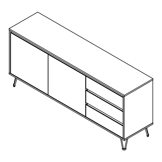
- Page 1 Media Console Sideboard CF4217...
-
Page 2: Part List
PART LIST Top Panel Bottom Panel Left Panel Right Panel Left Center Panel 1 PC 1 PC 1 PC 1 PC 1 PC Right Center Adjustable Top Front Rail Drawer Front Rail Back Rail Panel Shelf 1 PC 2 PCS 2 PCS 1 PC 2 PCS... -
Page 3: Hardware List
HARDWARE LIST Ø1/4" x L2" Ø1/4" x L19/32" Ø5/32" x L1 1/2" Ø1/8" x L5/8" Screw Bolt Long Screw Short Screw Cam Lock 8 PCS (Extra 1) 4 PCS (Extra 1) 15 PCS (Extra 1) 40 PCS (Extra 2) 29 PCS (Extra 2) Ø8 x L25mm 7/8"... - Page 4 Step 1. Attach cam bolts (part #6) to panels (parts A, C, D, F & M) using phillips head screwdriver. Note: Do not overtighten cam bolts. Stop tightening once threads on cam bolt are no longer visible. x 29 Step 2. Attach legs (parts #12 & #13) to bottom panel (part B) using bolts (part #2), short screws (part #4), allen wrench (part #14) and phillips head screwdriver.
- Page 5 Step 3. Attach drawer panels (parts N & O) to drawer front panel (part M) using wood dowels (part #7) and cam locks (part #5). Slide drawer bottom panel (part Q) into grooves of assembled unit (parts M, N & O). Attach drawer support (part T) to drawer front panel (part M) using wood dowel (part #7) and cam lock (part #5).
- Page 6 Step 5. Insert right back panel (part R) into grooves of assembled unit (parts F & J). Step 6. Attach right panel (part D) to assembled unit (parts I & J) using wood dowels (part #7) and cam locks (part #5). NOTE: Cam locks must rotate a full 180°.
- Page 7 Step 7. Attach top front rail (part H) to assembled unit (parts D & F) and left panel (part C) using wood dowels (part #7) and cam locks (part #5). NOTE: Cam locks must rotate a full 180°. See pictured insert. point arrow on cam lock toward adjacent hole...
- Page 8 Step 9. Attach left center panel (part E) to top panel (part A) using wood dowels (part #7) and cam locks (part #5). NOTE: Cam locks must rotate a full 180°. See pictured insert. point arrow on cam lock toward adjacent hole turn clockwise to fasten Step 10.
- Page 9 Step 11. Attach bottom panel (part B) to assembled unit (parts C, D, E & F) using wood dowels (part #7), screws (part #1) and allen wrench (part #14). Step 12. Carefully turn unit upright. Secure back brackets (part #10) at the corner of left back panels (part S) using short screws (part #4) and phillips head screwdriver.
- Page 10 Step 13. Place shelf supports (part #11) into desired position and slide adjustable shelves (part G) into place. C, E & F C & E E & F Step 14. Attach big hinges (part #8) to left door (part K) and small hinges (part #9) to right door (part L) using short screws (part #4) and phillips head screwdriver.
- Page 11 Step 15. Slide assembled drawers into place. Note: It is important to adjust levelers once fully assembled and upright. Extend adjustable leveler until it's firmly in contact with the floor. If relocating, adjust leveler as needed until it's firmly in contact with the floor in new Iocation.
- Page 12 Ø1/8" x L5/8" Ø5/32" x L1 1/2" Safety Wall Safety Strap Kit Wall Anchor Washer Short Screw Long Screw Strap 1 SET 2 PCS 4 PCS 2 PCS 2 PCS 2 PCS SAFETY WALL STRAP INSTALLATION Note: It is highly recommended to install this safety strap kit to prevent tipping, damage and/or injury.
Need help?
Do you have a question about the CF4217 and is the answer not in the manual?
Questions and answers