
Related Manuals for TLV CV5


Summary of Contents for TLV CV5
- Page 1 172-65238M-00 (CV5) 25 February 2003 ISO 9001/ ISO 14001 Manufacturer Kakogawa, Japan is approved by LRQA LTD. to ISO 9001/14001 Control Valve Copyright © 2000 by TLV CO., LTD. All rights reserve...
-
Page 2: Table Of Contents
Introduction Thank you for purchasing the Control Valve This product has been thoroughly inspected before being shipped from the factory. When the product is delivered, before doing anything else, check the specifications and external appearance to make sure nothing is out of the ordinary. -
Page 3: Safety Considerations
• The three types of cautionary items above are very important for safety: be sure to observe all of them as they relate to installation, use, maintenance, and repair. Furthermore, TLV accepts no responsibility for any accidents or damage occurring as a result of failure to observe these precautions. - Page 4 Be sure to use only the recommended components when repairing CAUTION the product, and NEVER attempt to modify the product in any way. Failure to observe these precautions may result in damage to the product and burns or other injury due to malfunction or the discharge of fluids.
-
Page 5: Specifications
Specifications DO NOT use this product outside the recommended operating pressure, temperature and other specification ranges. Improper use may result in such hazards as damage to the product or malfunctions which may lead to serious accidents. Local regulations may restrict the use of this product to below the conditions quoted. -
Page 6: Configuration
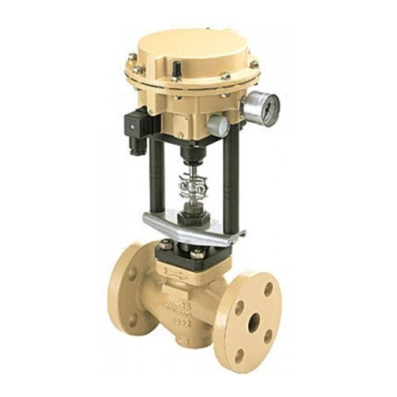
Configuration Fig. 1 Parts Name Parts Name Valve body Body Gasket Valve Bonnet Actuator Body Valve Seat Diaphragm Plug and Stem Actuator Stem Guide Bushing Positioner Case Stuffing Box V-ring Stem Bracket Stuffing Box Spring Yoke... -
Page 7: Installation
Installation DO NOT use this product outside the recommended operating pressure, temperature and other specification ranges. Improper use may result in such hazards as damage to the product or malfunctions which may lead to serious accidents. Local regulations may restrict the use of this product to below the conditions quoted. - Page 8 3. Mounting preparations Before attaching the actuator to the valve bonnet, actuators with close fail-safe action "Air to open" must be pressurized to slightly retract the actuator stem. Should no electric control signal be available during the mounting procedure, the hexagon nut (5) must be tightened (use a hexagonal wrench SW 36) to hold the pre- tensioned springs.
- Page 9 In case you need to deactivate the control valve action, deactivation may only be carried out by switching off the electric control signal, do not disconnect the supply air! 3.2 Pneumatic connections The electropneumatic actuator has tapped holes with G1/4 thread. The customary male connections for metal pipes or plastic hoses can be used.
-
Page 10: Operation
Operation DO NOT use this product outside the recommended operating pressure, temperature and other specification ranges. Improper use may result in such hazards as damage to the product or malfunctions which may lead to serious accidents. Local regulations may restrict the use of this product to below the conditions quoted. - Page 11 We recommend, nevertheless, that you check zero after the actuator has been attached to the valve. Proceed as described below: 1) Connect an ammeter to the control signal input and apply compressed air to the input "Supply". 2) Loosen the fastening screw and move away the cover plate (3, fig.4). 3) Pull the jumper from the pins to deactivate the tight-closing function.
- Page 12 3.2 Adjusting actuators with open fail-safe action "Air to close" Zero (starting point) 1) Use an ammeter to adjust the input signal to 20 mA. 2) Remove the cover plate and turn the zero adjuster (4, fig.4) until the plug stem just begins to leave its rest position.
-
Page 13: Maintenance
Maintenance Take measures to prevent people from coming into direct contact with product outlets. Failure to do so may result in burns or other injury from the discharge of fluids. Be sure to use only the recommended components when repairing the product, and NEVER attempt to modify the product in any way. - Page 14 1. Replacing seat and plug If the valve does not properly seal, dirt or damaged sealing edges could be the cause. In case of dirt, thoroughly clean the parts. In case of damaged sealing edges, replace for new ones. 1.1 Plug When replacing the plug, you should also replace the packing (4.2, fig.5) and the gasket (1.2, fig.5).
-
Page 15: Troubleshooting
Troubleshooting When disassembling or removing the product, wait until the internal pressure equals atmospheric pressure and the surface of the product has cooled to room temperature. Disassembling or removing the product when it is hot or under pressure may lead to discharge of fluids, causing burns, other injuries or damage. -
Page 16: Product Warranty
One year following product delivery. 1. Warranty Coverage TLV CO., LTD. warrants this product to the original purchaser to be free from defective materials and workmanship. Under this warranty, the product will be repaired or replaced at our option, without charge for parts or labor.
Need help?
Do you have a question about the CV5 and is the answer not in the manual?
Questions and answers