Table of Contents

Related Manuals for TLV CT16


Summary of Contents for TLV CT16
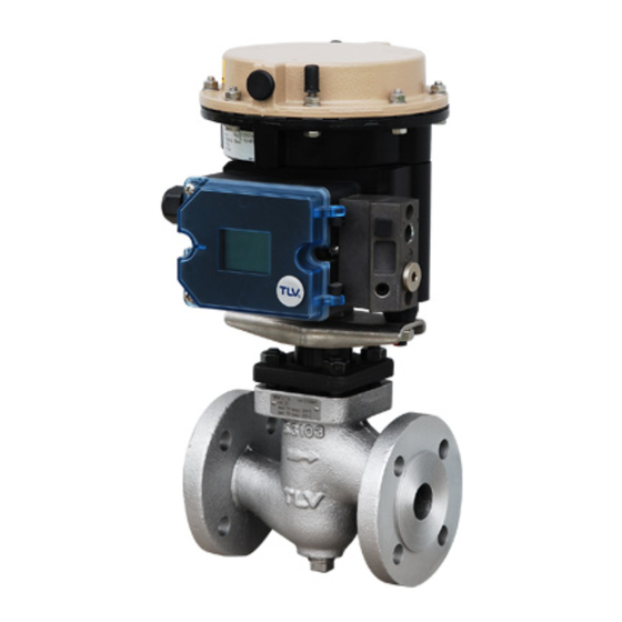
- Page 1 ISO 9001 ISO14001 Manufacturer Kakogawa, Japan is approved by LRQA Ltd. to ISO 9001/14001 Instruction Manual Electro-Pneumatic Control Valve CT16 (for Valve Unit) 172-65728M-04 Publication date 13 December 2023 Copyright © 2023 TLV CO., LTD.
-
Page 2: Table Of Contents
Table of Contents Introduction ..........................3 Safety Considerations ......................4 Specifications ........................... 6 Configuration ..........................7 Installation ..........................8 Maintenance ........................... 10 Disassembly/Reassembly ...................... 11 Troubleshooting ........................18 TLV EXPRESS LIMITED WARRANTY ................... 19 Service ........................... 21 Options ........................... 22... -
Page 3: Introduction
Introduction Thank you for purchasing the TLV electro-pneumatic control valve CT16. This product has been thoroughly inspected before being shipped from the factory. When the product is delivered, before doing anything else, check the specifications and external appearance to make sure nothing is out of the ordinary. Also be sure to read this manual carefully before use and follow the instructions to be sure of using the product properly. -
Page 4: Safety Considerations
• The three types of cautionary items above are very important for safety: be sure to observe all of them as they relate to installation, use, maintenance and repair. Furthermore, TLV accepts no responsibility for any accidents or damage occurring as a result of failure to observe these precautions. - Page 5 Caution Use only under conditions in which no freeze-up will occur. Freezing may damage the product, leading to fluid discharge, which may cause burns or other injury. Caution Use only under conditions in which no water hammer will occur. The impact of water hammer may damage the product, leading to fluid discharge, which may cause burns or other injury.
-
Page 6: Specifications
Specifications Caution Install properly and DO NOT use this product outside the recommended operating pressure, temperature and other specification ranges. Improper use may result in such hazards as damage to the product or malfunctions that may lead to serious accidents. Local regulations may restrict the use of this product to below the conditions quoted. -
Page 7: Configuration
Configuration Sizes 32, 40, 50 mm Part Name Maintenance Kit Repair Kit Body Flange Guide Bushing Valve Bonnet Nut Valve Bonnet ✔ Stuffing Box V-ring Packing ✔ Stuffing Box Washer ✔ Stuffing Box Spring ✔ Valve Plug & Stem ✔ ✔... -
Page 8: Installation
Installation Caution Install properly and DO NOT use this product outside the recommended operating pressure, temperature and other specification ranges. Improper use may result in such hazards as damage to the product or malfunctions that may lead to serious accidents. Local regulations may restrict the use of this product to below the conditions quoted. - Page 9 Piping support Install the product, paying attention to avoid excessive load, bending and vibration. Support the inlet and outlet pipes securely. Maintenance space Leave sufficient space for maintenance, inspection and repair. Drainage Port Usage Example The threaded condensate drainage port at the bottom of the body makes possible installation of a blow valve or steam/air trap.
-
Page 10: Maintenance
Maintenance Caution Take measures to prevent people from coming into direct contact with product outlets. Failure to do so may result in burns or other injury from the discharge of fluids. When disassembling or removing the product, wait until the internal pressure equals atmospheric pressure and the surface of the product has cooled to room temperature. -
Page 11: Disassembly/Reassembly
Disassembly/Reassembly Caution When disassembling or removing the product, wait until the internal pressure equals atmospheric pressure and the surface of the product has cooled to room temperature. Disassembling or removing the product when it is hot or under pressure may lead to discharge of fluids, causing burns, other injuries or damage. - Page 12 Removing/Reattaching the Stem Bracket Clamps Part Name During Disassembly During Reassembly ― Set the actuator air supply Set the actuator air supply pressure to 0 MPaG to pressure to 0 MPaG to maintain the valve in the fully closed position. Check maintain the valve in the fully to make sure the valve stem and actuator stem are closed position.
- Page 13 Disassembling/Reassembling the Valve and Actuator Sections Perform the following procedure before beginning disassembly. After connecting the air piping, operate the air pressure reducing valve to maintain the positioner air supply pressure at 0.38 MPaG. Connect a current generator or a controller for an operation signal input of 4 to 20 mA. Switch the positioner/actuator to manual mode to separate the valve from the actuator.
- Page 14 Disassembling/Reassembling the Body Section Part Name During Disassembly During Reassembly Guide Bushing Loosen slightly with a socket wrench to Consult the table of tightening torques make the following procedure easier. and tighten to the proper torque. Valve Bonnet Nut Remove with a socket wrench. Tighten the nuts evenly, while checking to make sure that there is no catching or biting when the...
- Page 15 Disassembling/Reassembling the Valve Seat Section Part Name During Disassembly During Reassembly Valve Seat 15 to 25 mm: Remove with a socket Over tightening the valve seat may wrench lead to damage the valve seat and/or 32 to 50 mm: Remove with a thin wall body;...
- Page 16 Table of Tightening Torques Distance Across Part Name & No. Size (mm) Torque (N·m) Flats (mm) Guide Bushing 3 15 to 80 Bonnet Flange Nut 12 15 to 25 16/17 32 to 50 18/19 Valve Seat 13 15 to 25 40, 50 Valve Bonnet Nut 4 15 to 50...
- Page 17 Exploded View Part Name Part Name Body Valve Plug & Stem Flange Valve Bonnet Gasket Guide Bushing Bonnet Flange Bolt Valve Bonnet Nut Bonnet Flange Nut Valve Bonnet Valve Seat Stuffing Box V-ring Packing Nameplate Stuffing Box Washer Drain Plug Stuffing Box Spring Silencer Front: Model, size, date of manufacture / Back: Spring range, Cv value, etc.
-
Page 18: Troubleshooting
Troubleshooting Caution When disassembling or removing the product, wait until the internal pressure equals atmospheric pressure and the surface of the product has cooled to room temperature. Disassembling or removing the product when it is hot or under pressure may lead to discharge of fluids, causing burns, other injuries or damage. -
Page 19: Tlv Express Limited Warranty
Subject to the limitations set forth below, TLV CO., LTD., a Japanese corporation ("TLV"), warrants that products which are sold by it, TLV International Inc. ("TII") or one of its group companies excluding TLV Corporation (a corporation of the United States of America), (hereinafter the "Products") are designed and manufactured by TLV, conform to the... - Page 20 HEREBY, INCLUDING THE IMPLIED WARRANTIES OF MERCHANTABILITY AND FITNESS FOR A PARTICULAR PURPOSE, DO NOT COVER, AND NEITHER TLV, TII NOR ITS TLV GROUP COMPANIES WILL IN ANY EVENT BE LIABLE FOR, INCIDENTAL OR CONSEQUENTIAL DAMAGES, INCLUDING, BUT NOT LIMITED TO LOST PROFITS, THE COST OF DISASSEMBLY AND SHIPMENT OF THE DEFECTIVE PRODUCT, INJURY TO OTHER PROPERTY, DAMAGE TO BUYER’S OR THE FIRST...
-
Page 21: Service
Service For Service or Technical Assistance: Contact your TLV representative or your regional TLV office. In Europe: Tel: [49]-(0)7263-9150-0 Daimler-Benz-Straße 16-18, 74915 Waibstadt, Germany Tel: [44]-(0)1242-227223 Units 7 & 8, Furlong Business Park, Bishops Cleeve, Gloucestershire GL52 8TW, U.K. Tel:... -
Page 22: Options
Options Caution Install properly and DO NOT use this product outside the recommended operating pressure, temperature and other specification ranges. Improper use may result in such hazards as damage to the product or malfunctions that may lead to serious accidents. Local regulations may restrict the use of this product to below the conditions quoted.
Need help?
Do you have a question about the CT16 and is the answer not in the manual?
Questions and answers