
Related Manuals for TLV CV-COS-20


Summary of Contents for TLV CV-COS-20
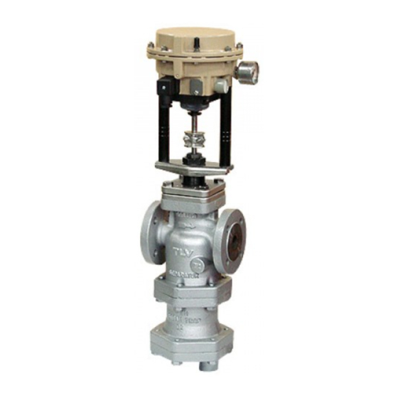
- Page 1 172-654741MA-01 (CV-COS-20/CV-COS-20D) 7 October 2021 Electro-Pneumatic Control Valve with Built-in Separator and Steam Trap CV-COS-20/CV-COS-20D (for Valve Unit) Copyright © 2021 by TLV CO., LTD. All rights reserved...
-
Page 2: Table Of Contents
Service ................28 Options ................29 Introduction Thank you for purchasing the TLV electro-pneumatic control valve with built-in separator and steam trap CV-COS-20/CV-COS-20D. This product has been thoroughly inspected before being shipped from the factory. When the product is delivered, before doing anything else, check the specifications and external appearance to make sure nothing is out of the ordinary. -
Page 3: Safety Considerations
The three types of cautionary items above are very important for safety: be sure to observe all of them as they relate to installation, use, maintenance and repair. Furthermore, TLV accepts no responsibility for any accidents or damage occurring as a result of failure to observe these precautions. - Page 4 When using this product, NEVER stand close to, or leave tools anywhere near, moving parts, such as the shaft. Contact with moving parts or objects becoming caught in moving parts could lead to injury or damage or other accidents. 172-654741MA-01 (CV-COS-20/CV-COS-20D) 7 Oct 2021...
-
Page 5: Specifications
*Maximum allowable pressure (PMA) and maximum allowable temperature (TMA) are PRESSURE SHELL DESIGN CONDITIONS, NOT OPERATING CONDITIONS. **Valve No. is displayed for products with options. This item is omitted from the nameplate when there are no options. 172-654741MA-01 (CV-COS-20/CV-COS-20D) 7 Oct 2021... -
Page 6: Configuration
) only 32 Actuator Stem 33 Fixing Nut *Replacement parts are available only in the following kits: A = Maintenance Kit B = Repair Kit C = Repair Kit for Trap Valve Seat D = Float 172-654741MA-01 (CV-COS-20/CV-COS-20D) 7 Oct 2021... - Page 7 33 Fixing Nut 34 Baffle Nut 35 Baffle *Replacement parts are available only in the following kits: A = Maintenance Kit B = Repair Kit C = Repair Kit for Trap Valve Seat D = Float 172-654741MA-01 (CV-COS-20/CV-COS-20D) 7 Oct 2021...
- Page 8 31 Stem Bracket Clamps 32 Actuator Stem 33 Fixing Nut *Replacement parts are available only in the following kits: A = Maintenance Kit B = Repair Kit C = Repair Kit for Trap Valve Seat D = Float 172-654741MA-01 (CV-COS-20/CV-COS-20D) 7 Oct 2021...
- Page 9 33 Fixing Nut 34 Baffle Nut 35 Baffle *Replacement parts are available only in the following kits: A = Maintenance Kit B = Repair Kit C = Repair Kit for Trap Valve Seat D = Float 172-654741MA-01 (CV-COS-20/CV-COS-20D) 7 Oct 2021...
-
Page 10: Installation
3. Installing the control valve Lift the assembled product using hoisting equipment such as cranes and forklifts. Do not lift the assembled product using only the eye bolt. (See Fig. 2) Fig. 2 Hoisting the control valve 172-654741MA-01 (CV-COS-20/CV-COS-20D) 7 Oct 2021... - Page 11 15 degrees in the plane perpendicular to the steam flow line. CV-COS-20 CV-COS-20D 6. Piping support Install the product, paying attention to avoid excessive load, bending and vibration. Support the inlet and outlet pipes securely. CV-COS-20 CV-COS-20D 172-654741MA-01 (CV-COS-20/CV-COS-20D) 7 Oct 2021...
- Page 12 Though the product adequately performs the function of a shut-off valve initially, extended use will result in a drop in its performance as an isolation valve. Be sure to install a separate shut-off or automatic valve if complete isolation is needed. 172-654741MA-01 (CV-COS-20/CV-COS-20D) 7 Oct 2021...
- Page 13 If air quality results in operation failure, the entire actuator unit (including the integrated positioner) must be replaced. If there is a problem in operation, determine the cause using the “Troubleshooting” section in this manual. 172-654741MA-01 (CV-COS-20/CV-COS-20D) 7 Oct 2021...
-
Page 14: Maintenance
Stuffing Box V-ring Packing: Check for warping or damage Valve Plug & Stem, Valve Seat: Check for damage or scratches Separator Screen: Check for clogging and corrosion Trap Valve Seat: Check for scratches, dents, etc. Float: Check for scratches, dents, etc. 172-654741MA-01 (CV-COS-20/CV-COS-20D) 7 Oct 2021... -
Page 15: Disassembly/Reassembly
Remove the fixing nut connecting Consult the table of tightening the actuator and the valve bonnet torques and tighten to the proper while keeping the actuator stem in torque the raised position Valve Bonnet Fixing Nut Stem Bracket Clamps 172-654741MA-01 (CV-COS-20/CV-COS-20D) 7 Oct 2021... - Page 16 (valve leakage) may result: give the proper attention to the adjustment procedure NOTE: Be careful not to pinch your fingers between the valve stem and actuator stem! Stem Connector Nut Locknut 172-654741MA-01 (CV-COS-20/CV-COS-20D) 7 Oct 2021...
- Page 17 Fig. 4 Actuator Stem descends Stem Connector Nut NOTE: Be careful not to pinch Locknut your fingers Fig. 5 Travel Indicator Scale Mounting Bolt Stem Bracket Clamps Travel Indicator Scale Travel Indicator Scale Mounting Bolt 172-654741MA-01 (CV-COS-20/CV-COS-20D) 7 Oct 2021...
- Page 18 Be careful Pull up the stem not to pinch connector nut and your fingers the valve stem Fig. 5 Travel Indicator Scale Stem Bracket Mounting Bolt Clamps Travel Indicator Scale Travel Indicator Scale Mounting Bolt 172-654741MA-01 (CV-COS-20/CV-COS-20D) 7 Oct 2021...
- Page 19 Stuffing Box Pull up and out Reinsert Washer/ Stuffing Box Spring Guide Bushing Stuffing Box V-Ring Packing Stuffing Box Washer Stuffing Box Spring Cut view of Stuffing Box V-Ring Packing 172-654741MA-01 (CV-COS-20/CV-COS-20D) 7 Oct 2021...
- Page 20 Replace with a new gasket; make sure that the Gasket clean sealing surfaces gasket does not protrude from the housing in the body; DO NOT coat with anti-seize Valve Bonnet Section Valve Bonnet Valve Plug Gasket Body Section 172-654741MA-01 (CV-COS-20/CV-COS-20D) 7 Oct 2021...
- Page 21 This procedure requires a special Over-tightening could result in tool; contact TLV for details damage to the valve seat and body; consult the table of tightening torques and tighten to the proper torque Valve Seat 172-654741MA-01 (CV-COS-20/CV-COS-20D) 7 Oct 2021...
- Page 22 Insert it into the groove in the main body Wave Spring Remove the wave spring Insert it into the groove in the trap body Separator Screen Separator Body Separator Gasket Separator Body Wave Spring Separator Body Bolt 172-654741MA-01 (CV-COS-20/CV-COS-20D) 7 Oct 2021...
- Page 23 Float Cover Bolt Bolt Spring Washer Float Cover Float Trap Cover Float Trap Cover Gasket Trap Valve Seat Trap Valve Seat Trap Valve Seat Trap Cover Trap Valve Seat Gasket Gasket Trap Cover Trap Cover Bolt 172-654741MA-01 (CV-COS-20/CV-COS-20D) 7 Oct 2021...
- Page 24 Actuator area (1 Nm 10 kgcm) NOTE: -Coat all threaded portions with anti-seize. -If drawings or other special documentation were supplied for the product, any torque given there takes precedence over values shown here. 172-654741MA-01 (CV-COS-20/CV-COS-20D) 7 Oct 2021...
- Page 25 Valve Seat Gasket Separator Body Main Body Bolt Baffle Nut Baffle Float Cover Bolt Spring Washer Float Cover Float Trap Cover Gasket Trap Valve Seat Gasket Trap Valve Seat Gasket Trap Cover Trap Cover Bolt 172-654741MA-01 (CV-COS-20/CV-COS-20D) 7 Oct 2021...
-
Page 26: Troubleshooting
Output piping is clogged Check the outlet piping Clean or modify the piping The trap valve seat is Check the trap valve Clean or replace with a new clogged seat trap valve seat 172-654741MA-01 (CV-COS-20/CV-COS-20D) 7 Oct 2021... -
Page 27: Tlv Express Limited Warranty
Subject to the limitations set forth below, TLV CO., LTD., a Japanese corporation (“TLV”), warrants that products which are sold by it, TLV International Inc. (“TII”) or one of its group companies excluding TLV Corporation (a corporation of the United States of America), (hereinafter the “Products”) are designed and manufactured by... - Page 28 WARRANTY NOT NEGATED HEREBY, AND ANY IMPLIED WARRANTY NOT NEGATED HEREBY, INCLUDING THE IMPLIED WARRANTIES OF MERCHANTABILITY AND FITNESS FOR A PARTICULAR PURPOSE, DO NOT COVER, AND NEITHER TLV, TII NOR ITS TLV GROUP COMPANIES WILL IN ANY EVENT BE LIABLE FOR, INCIDENTAL OR...
-
Page 29: Service
Service For Service or Technical Assistance: Contact your TLV representative or your regional TLV office. In Europe: Tel: [49]-(0)7263-9150-0 Daimler-Benz-Straße 16-18, 74915 Waibstadt, Germany Fax: [49]-(0)7263-9150-50 Tel: [44]-(0)1242-227223 Units 7 & 8, Furlong Business Park, Bishops Cleeve, Gloucestershire GL52 8TW, U.K. -
Page 30: Options
1. Remove the plug (optional) from the main body and install the blow/purge valve. 2. Open the blow/purge valve and blow any residual dirt and scale off of the screen. 3. Periodically activate the blow/purge valve to keep the system free of dirt and scale. 172-654741MA-01 (CV-COS-20/CV-COS-20D) 7 Oct 2021...
Need help?
Do you have a question about the CV-COS-20 and is the answer not in the manual?
Questions and answers