Table of Contents
Advertisement
Quick Links
Advertisement
Table of Contents

Related Manuals for Apogee MQ-650


Summary of Contents for Apogee MQ-650
-
Page 1: Owner's Manual
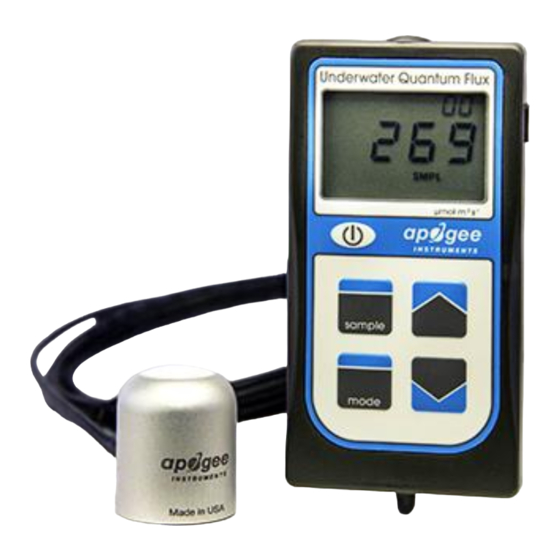
OWNER’S MANUAL UNDERWATER EPAR METER Models MQ-650 Rev: 30-Mar-2022 APOGEE INSTRUMENTS, INC. | 721 WEST 1800 NORTH, LOGAN, UTAH 84321, USA TEL: (435) 792-4700 | FAX: (435) 787-8268 | WEB: APOGEEINSTRUMENTS.COM Copyright © 2022 Apogee Instruments, Inc. -
Page 2: Table Of Contents
Specifications ................................... 6 Deployment and Installation ..............................8 Battery Installation and Replacement ............................ 10 Operation and Measurement ..............................11 Apogee AMS Software ................................14 Maintenance and Recalibration ............................. 16 Troubleshooting and Customer Support ..........................17 Return and Warranty Policy ..............................19... -
Page 3: Certificate Of Compliance
RoHS 3 compliant using exemption 6c. Further note that Apogee Instruments does not specifically run any analysis on our raw materials or end products for the presence of these substances, but we rely on the information provided to us by our material suppliers. -
Page 4: Introduction
The immersion effect correction factor for Apogee ePAR sensors (model MQ-610 and SQ-610 series) is 1.25. The MQ-650 ePAR meter is designed for underwater measurements, and already applies the immersion effect correction factor to the meter’s readings through firmware. -
Page 5: Sensor Models
SENSOR MODELS Apogee MQ series ePAR meters covered in this manual are self-contained and come complete with handheld meter and sensor. A sensor’s model number and serial number are located on a label on the backside of the handheld meter. -
Page 6: Specifications
2 m of two conductor, shielded, twisted-pair wire; additional cable available; TPR jacket Calibration Traceability Apogee MQ series ePAR meters are calibrated through side-by-side comparison to the mean of four transfer standard sensors under a reference lamp. The reference sensors are recalibrated with a 200 W quartz halogen... - Page 7 Spectral Response Mean spectral response measurements of four replicate Apogee MQ-600 series ePAR Sensors. Incremental spectral response measurements were made at 10 nm increments across a wavelength range of 370 to 800 nm in a monochromator with an attached electric light source.
- Page 8 Directional, or cosine, response is defined as the measurement error at a specific angle of radiation incidence. Error for Apogee MQ-600 series ePAR Sensor is approximately ± 2 % and ± 5 % at solar zenith angles of 45° and 75°, respectively.
-
Page 9: Deployment And Installation
To accurately measure PFD incident on a horizontal surface, the sensor must be level. The AL-100 accessory leveling plate is recommended for use with the MQ-650 to ensure the sensor is level when attached to a cross-arm. The bubble-level in the plate makes leveling simple and accurate. -
Page 10: Battery Installation And Replacement
BATTERY INSTALLATION AND REPLACEMENT Use a Phillips head screwdriver to remove the screw from the battery cover. Remove the battery cover by slightly lifting and sliding the outer edge of the cover away from the meter. To power the meter, slide the included battery (CR2320) into the battery holder, after removing the battery door from the meter’s back panel. -
Page 11: Operation And Measurement
OPERATION AND MEASUREMENT MQ series ePAR meters are designed with a user-friendly interface allowing quick and easy measurements. Press the power button to activate the LCD display. After two minutes of non-activity the meter will revert to sleep mode and the display will shut off to conserve battery life. Press the mode button to access the main menu, where manual or automatic logging are selected, and where the meter can be reset. - Page 12 Downloading the stored measurements will require the AC-100 communication cable and software (sold separately). The meter outputs data using the UART protocol and requires the AC-100 to convert from UART to USB, so standard USB cables will not work. Set up instructions and software can be downloaded from the Apogee website (http://www.apogeeinstruments.com/ac-100-communcation-cable/).
- Page 13 The MQ-650 sensor has an immersion effect correction factor of 1.25. The immersion effect correction factor is already accounted for in the MQ-650 meter firmware so there is no need to apply the correction factor to your measurements. If you wish to use your meter to make measurements in air, simply divide the measured number by the immersion effect (1.25).
-
Page 14: Apogee Ams Software
APOGEE AMS SOFTWARE Downloading data to a computer requires the AC-100 communication cable and the free ApogeeAMS software. The meter outputs data using the UART protocol and requires the AC-100 to convert from UART to USB, so standard USB cables will not work. - Page 15 “Daily Totals” shows all of the saved Daily Light Integral (DLI) totals per day. Click “30 Min Avg” to see the meter’s 99, 30-minute averages. To analyze the data, click on “File” and “Save As” to save the data as a .csv file. Or, you can highlight the numbers, copy, and paste them into a blank Excel spreadsheet.
-
Page 16: Maintenance And Recalibration
Although Apogee sensors are very stable, nominal accuracy drift is normal for all research-grade sensors. To ensure maximum accuracy, we generally recommend sensors are sent in for recalibration every two years,... -
Page 17: Troubleshooting And Customer Support
TROUBLESHOOTING AND CUSTOMER SUPPORT Verify Functionality Pressing the power button should activate the LCD and provide a real-time PPFD reading. Direct the sensor head toward a light source and verify the PPFD reading responds. Increase and decrease the distance from the sensor to the light source to verify that the reading changes proportionally (decreasing PPFD with increasing distance and increasing PPFD with decreasing distance). - Page 18 See Apogee webpage for further details on how to extend...
-
Page 19: Return And Warranty Policy
RETURN AND WARRANTY POLICY RETURN POLICY Apogee Instruments will accept returns within 30 days of purchase as long as the product is in new condition (to be determined by Apogee). Returns are subject to a 10 % restocking fee. WARRANTY POLICY... - Page 20 84321, USA 5. Upon receipt, Apogee Instruments will determine the cause of failure. If the product is found to be defective in terms of operation to the published specifications due to a failure of product materials or craftsmanship, Apogee Instruments will repair or replace the items free of charge.
Need help?
Do you have a question about the MQ-650 and is the answer not in the manual?
Questions and answers