Table of Contents
Advertisement
Quick Links
MEETINSTRUMENTATIE
Turfschipper 114 | 2292 JB Wateringen | Tel. +31 (0)174 272330 | www.catec.nl | info@catec.nl
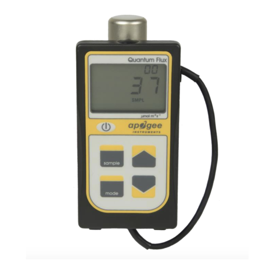
OWNER'S MANUAL
QUANTUM METER
Models MQ-501
APOGEE INSTRUMENTS, INC. | 721 WEST 1800 NORTH, LOGAN, UTAH 84321, USA
TEL: (435) 792-4700 | FAX: (435) 787-8268 | WEB: APOGEEINSTRUMENTS.COM
Copyright © 2018 Apogee Instruments, Inc.
Advertisement
Table of Contents

Related Manuals for Apogee MQ-501


Summary of Contents for Apogee MQ-501
-
Page 1: Owner's Manual
Turfschipper 114 | 2292 JB Wateringen | Tel. +31 (0)174 272330 | www.catec.nl | info@catec.nl OWNER’S MANUAL QUANTUM METER Models MQ-501 APOGEE INSTRUMENTS, INC. | 721 WEST 1800 NORTH, LOGAN, UTAH 84321, USA TEL: (435) 792-4700 | FAX: (435) 787-8268 | WEB: APOGEEINSTRUMENTS.COM Copyright © 2018 Apogee Instruments, Inc. -
Page 2: Table Of Contents
TABLE OF CONTENTS Owner’s Manual ....................................1 Certificate of Compliance ................................. 3 Introduction ..................................... 4 Sensor Models ..................................5 Specifications ................................... 6 Deployment and Installation ..............................9 Operation and Measurement ..............................10 Maintenance and Recalibration ............................. 14 Troubleshooting and Customer Support ..........................16 Return and Warranty Policy .............................. -
Page 3: Certificate Of Compliance
(PBB), polybrominated diphenyls (PBDE). Further note that Apogee Instruments does not specifically run any analysis on our raw materials or end products for the presence of these substances, but rely on the information provided to us by our material suppliers. -
Page 4: Introduction
(transmitted) PPFD measurement in the same environments. Apogee Instruments MQ-501 quantum meters consist of a handheld meter, dedicated quantum sensor that is connected by cable to an anodized aluminum housing, and AM-001 Meter Mounting Bracket. Sensors consist of a cast acrylic diffuser (filter), photodiode, and are potted solid with no internal air space. -
Page 5: Sensor Models
SENSOR MODELS Apogee MQ series quantum meters covered in this manual are self-contained and come complete with handheld meter, sensor, and AM-001 Meter Mounting Bracket. Sensor model number and serial number are located on a label on the backside of the handheld... -
Page 6: Specifications
TPR jacket Calibration Traceability Apogee MQ series quantum meters are calibrated through side-by-side comparison to the mean of four Apogee model SQ-110 or SQ-120 transfer standard quantum sensors under high output T5 cool white fluorescent lamps. The transfer standard quantum sensors are calibrated through side-by-side comparison to the mean of at least three LI-COR model LI-190 reference quantum sensors under high output T5 cool white fluorescent lamps. - Page 7 Spectral Response Mean spectral response measurements of six replicate Apogee SQ-100 (original) and SQ-500 (full-spectrum) series quantum sensor. Spectral response measurements were made at 10 nm increments across a wavelength range of 300 to 800 nm in a monochromator with an attached electric light source.
- Page 8 Directional, or cosine, response is defined as the measurement error at a specific angle of radiation incidence. Error for Apogee SQ series quantum sensors is approximately ± 2 % and ± 5 % at solar zenith angles of 45° and 75°, respectively.
-
Page 9: Deployment And Installation
DEPLOYMENT AND INSTALLATION The MQ-501 is designed for spot-check measurements. To accurately measure PFFD incident on a horizontal surface, the sensor must be level. For this purpose, the meter comes with the AM-001 meter mounting bracket to mount the sensor on a horizontal plane to the meter for simple spot-check measurements. -
Page 10: Operation And Measurement
OPERATION AND MEASUREMENT MQ series quantum meters are designed with a user-friendly interface allowing quick and easy measurements. To power the meter, slide the included battery (CR2320) into the battery holder, after removing the battery door from the meter’s back panel. The positive side (designated by a “+” sign) should be facing out from the meter circuit board. - Page 11 Downloading the stored measurements will require the AC-100 communication cable and software (sold separately). The meter outputs data using the UART protocol and requires the AC-100 to convert from UART to USB, so standard USB cables will not work. Set up instructions and software can be downloaded from the Apogee website (http://www.apogeeinstruments.com/ac-100-communcation-cable/).
- Page 12 Spectral Errors for PPFD and YPFD Measurements with Apogee SQ Series Quantum Sensors SQ-100 Series SQ-500 Series Radiation Source (Error Calculated Relative to Sun, Clear Sky) PPFD Error [%] PPFD Error [%] Sun (Clear Sky) Sun (Cloudy Sky) Reflected from Grass Canopy...
- Page 13 (PPFD) and yield photon flux density (YPFD) for multiple different radiation sources. YPFD is approximately 90 % of PPFD. Measurements were made with a spectroradiometer (Apogee Instruments model PS-200) and weighting factors shown in previous figure were used to calculate PPFD and YPFD.
-
Page 14: Maintenance And Recalibration
MAINTENANCE AND RECALIBRATION Moisture or debris on the diffuser is a common cause of low readings. The sensor has a domed diffuser and housing for improved self-cleaning from rainfall, but materials can accumulate on the diffuser (e.g., dust during periods of low rainfall, salt deposits from evaporation of sea spray or sprinkler irrigation water) and partially block the optical path. - Page 15 Homepage of the Clear Sky Calculator. Two calculators are available: one for quantum sensors (PPFD) and one for pyranometers (total shortwave radiation). Clear Sky Calculator for quantum sensors. Site data are input in blue cells in middle of page and an estimate of PPFD is returned on right-hand side of page.
-
Page 16: Troubleshooting And Customer Support
TROUBLESHOOTING AND CUSTOMER SUPPORT Verify Functionality Pressing the power button should activate the LCD and provide a real-time PPFD reading. Direct the sensor head toward a light source and verify the PPFD reading responds. Increase and decrease the distance from the sensor to the light source to verify that the reading changes proportionally (decreasing PPFD with increasing distance and increasing PPFD with decreasing distance). - Page 17 See Apogee webpage for further details on how to extend sensor cable length: (http://www.apogeeinstruments.com/how-to-make-a-weatherproof-cable-splice/).
-
Page 18: Return And Warranty Policy
RETURN AND WARRANTY POLICY RETURN POLICY Apogee Instruments will accept returns within 30 days of purchase as long as the product is in new condition (to be determined by Apogee). Returns are subject to a 10 % restocking fee. WARRANTY POLICY... - Page 19 5. Upon receipt, Apogee Instruments will determine the cause of failure. If the product is found to be defective in terms of operation to the published specifications due to a failure of product materials or craftsmanship, Apogee Instruments will repair or replace the items free of charge.
Need help?
Do you have a question about the MQ-501 and is the answer not in the manual?
Questions and answers