Table of Contents
Advertisement
Quick Links
Advertisement
Table of Contents

Subscribe to Our Youtube Channel
Related Manuals for Apogee MQ-210


Summary of Contents for Apogee MQ-210
-
Page 1: Owner's Manual
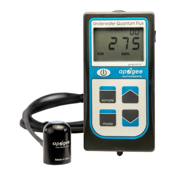
OWNER’S MANUAL UNDERWATER QUANTUM METER Model MQ-210 Rev: 28-Oct-2020 APOGEE INSTRUMENTS, INC. | 721 WEST 1800 NORTH, LOGAN, UTAH 84321, USA TEL: (435) 792-4700 | FAX: (435) 787-8268 | WEB: APOGEEINSTRUMENTS.COM Copyright © 2021 Apogee Instruments, Inc. -
Page 2: Table Of Contents
TABLE OF CONTENTS Owner’s Manual ....................................1 Certificate of Compliance ................................. 3 Introduction ..................................... 4 Sensor Models ..................................5 Specifications ................................... 6 Deployment and Installation ..............................9 Operation and Measurement ..............................10 Maintenance and Recalibration ............................. 15 Troubleshooting and Customer Support ..........................17 Return and Warranty Policy .............................. -
Page 3: Certificate Of Compliance
RoHS 3 compliant using exemption 6c. Further note that Apogee Instruments does not specifically run any analysis on our raw materials or end products for the presence of these substances, but rely on the information provided to us by our material suppliers. -
Page 4: Introduction
The immersion effect correction factor for Apogee original quantum sensors (model MQ-200 and SQ-200 series) is 1.08. The MQ-210 quantum meter is designed for underwater measurements, and already applies the immersion effect correction factor to the meter’s readings through firmware. -
Page 5: Sensor Models
SENSOR MODELS Apogee MQ series quantum meters covered in this manual are self-contained and come complete with handheld meter and sensor. Sensor model number and serial number are located on a label on the backside of the handheld meter. -
Page 6: Specifications
UV stability, flexibility in cold conditions) Calibration Traceability Apogee MQ series quantum meters are calibrated through side-by-side comparison to the mean of four transfer standard quantum sensors under high output T5 cool white fluorescent lamps. The reference quantum sensors are recalibrated with a 200 W quartz halogen lamp traceable to the National Institute of Standards and Technology (NIST). - Page 7 Spectral Response Mean spectral response of six SQ series quantum sensors (error bars represent two standard deviations above and below mean) compared to PPFD weighting function. Spectral response measurements were made at 10 nm increments across a wavelength range of 300 to 800 nm in a monochromator with an attached electric light source.
- Page 8 Directional, or cosine, response is defined as the measurement error at a specific angle of radiation incidence. Error for Apogee SQ series quantum sensors is approximately ± 2 % and ± 5 % at solar zenith angles of 45° and 75°, respectively.
-
Page 9: Deployment And Installation
To accurately measure PFFD incident on a horizontal surface, the sensor must be level. The AL-100 accessory leveling plate is recommended for use with the MQ-210 to ensure the sensor is level when attached to a cross-arm. The bubble-level in the plate makes leveling simple and accurate. -
Page 10: Operation And Measurement
OPERATION AND MEASUREMENT MQ series quantum meters are designed with a user-friendly interface allowing quick and easy measurements. To power the meter, slide the included battery (CR2320) into the battery holder, after removing the battery door from the meter’s back panel. The positive side (designated by a “+” sign) should be facing out from the meter circuit board. - Page 11 Downloading the stored measurements will require the AC-100 communication cable and software (sold separately). The meter outputs data using the UART protocol and requires the AC-100 to convert from UART to USB, so standard USB cables will not work. Set up instructions and software can be downloaded from the Apogee website (http://www.apogeeinstruments.com/ac-100-communcation-cable/).
- Page 12 T5 cool white fluorescent lamps and will read approximately 12 % low in sunlight. In addition to PPFD measurements, Apogee MQ series quantum meters can also be used to measure yield photon flux density (YPF): photon flux weighted according to the plant photosynthetic action spectrum (McCree, 1972) and summed.
- Page 13 Spectral Errors for PPFD and YPFD Measurements with Apogee MQ Series Quantum Meters Radiation Source (Error Calculated Relative to Sun, Clear Sky) PPFD Error YPFD Error Sun (Clear Sky) Sun (Cloudy Sky) Reflected from Grass Canopy -6.3 Reflected from Deciduous Canopy -7.0...
- Page 14 The MQ-210 sensor has an immersion effect correction factor of 1.08. The immersion effect correction factor is already accounted for in the MQ-210 meter firmware so there is no need to apply the correction factor to your measurements. If you wish to use your meter to make measurements in air, simply divide the measured number by the immersion effect (1.08).
-
Page 15: Maintenance And Recalibration
Although Apogee sensors are very stable, nominal accuracy drift is normal for all research-grade sensors. To ensure maximum accuracy, we generally recommend sensors are sent in for recalibration every two years, although you can often wait longer according to your particular tolerances. - Page 16 Homepage of the Clear Sky Calculator. Two calculators are available: one for quantum sensors (PPFD) and one for pyranometers (total shortwave radiation). Clear Sky Calculator for quantum sensors. Site data are input in blue cells in middle of page and an estimate of PPFD is returned on right-hand side of page.
-
Page 17: Troubleshooting And Customer Support
TROUBLESHOOTING AND CUSTOMER SUPPORT Verify Functionality Pressing the power button should activate the LCD and provide a real-time PPFD reading. Direct the sensor head toward a light source and verify the PPFD reading responds. Increase and decrease the distance from the sensor to the light source to verify that the reading changes proportionally (decreasing PPFD with increasing distance and increasing PPFD with decreasing distance). - Page 18 See Apogee webpage for further details on how to extend sensor cable length: (http://www.apogeeinstruments.com/how-to-make-a-weatherproof-cable-splice/).
-
Page 19: Return And Warranty Policy
RETURN AND WARRANTY POLICY RETURN POLICY Apogee Instruments will accept returns within 30 days of purchase as long as the product is in new condition (to be determined by Apogee). Returns are subject to a 10 % restocking fee. WARRANTY POLICY... - Page 20 84321, USA 5. Upon receipt, Apogee Instruments will determine the cause of failure. If the product is found to be defective in terms of operation to the published specifications due to a failure of product materials or craftsmanship, Apogee Instruments will repair or replace the items free of charge.
Need help?
Do you have a question about the MQ-210 and is the answer not in the manual?
Questions and answers