Table of Contents
Advertisement
Quick Links
R-410A
DEZ/DEQ/DEX 024-060
General . . . . . . . . . . . . . . . . . . . . . . . . . . . . . . . . . . . . . . . . . . 2
Installation . . . . . . . . . . . . . . . . . . . . . . . . . . . . . . . . . . . . . . . . 3
Limitations . . . . . . . . . . . . . . . . . . . . . . . . . . . . . . . . . . . . . . 3
Location. . . . . . . . . . . . . . . . . . . . . . . . . . . . . . . . . . . . . . . . 4
Rigging And Handling . . . . . . . . . . . . . . . . . . . . . . . . . . . . . 5
Ductwork . . . . . . . . . . . . . . . . . . . . . . . . . . . . . . . . . . . . . . . 9
Roof Curb . . . . . . . . . . . . . . . . . . . . . . . . . . . . . . . . . . . . . . 9
Filters . . . . . . . . . . . . . . . . . . . . . . . . . . . . . . . . . . . . . . . . . 9
Condensate Drain . . . . . . . . . . . . . . . . . . . . . . . . . . . . . . . . 9
Service Access . . . . . . . . . . . . . . . . . . . . . . . . . . . . . . . . . . 9
Thermostat . . . . . . . . . . . . . . . . . . . . . . . . . . . . . . . . . . . . . 9
Power And Control Wiring. . . . . . . . . . . . . . . . . . . . . . . . . . 9
Compressors. . . . . . . . . . . . . . . . . . . . . . . . . . . . . . . . . . . 18
Phasing . . . . . . . . . . . . . . . . . . . . . . . . . . . . . . . . . . . . . . . 18
Airflow Performance . . . . . . . . . . . . . . . . . . . . . . . . . . . . . . . 19
1 DEZ/DEQ Unit Limitations . . . . . . . . . . . . . . . . . . . . . . . . . 4
2 DEX Unit Limitations . . . . . . . . . . . . . . . . . . . . . . . . . . . . . 4
3 DEZ 4 Point Load Weight . . . . . . . . . . . . . . . . . . . . . . . . . 5
4 DEQ 4 Point Load Weight . . . . . . . . . . . . . . . . . . . . . . . . . 5
5 DEX 4 Point Load Weight . . . . . . . . . . . . . . . . . . . . . . . . . 6
6 DEZ/DEQ/DEX Unit Accessory Weights . . . . . . . . . . . . . . 6
7 DEZ Unit Dimensions Front . . . . . . . . . . . . . . . . . . . . . . . 6
8 DEQ Unit Dimensions Front . . . . . . . . . . . . . . . . . . . . . . . 6
9 DEX Unit Dimensions Front . . . . . . . . . . . . . . . . . . . . . . . 7
10 DEZ/DEQ/DEX Unit Clearances . . . . . . . . . . . . . . . . . . . . 7
11 DEZ Electrical Data . . . . . . . . . . . . . . . . . . . . . . . . . . . . . 12
12 DEQ Electrical Data . . . . . . . . . . . . . . . . . . . . . . . . . . . . 13
13 DEX Electrical Data . . . . . . . . . . . . . . . . . . . . . . . . . . . . . 14
14 DEZ Physical Data . . . . . . . . . . . . . . . . . . . . . . . . . . . . . 15
15 DEQ Physical Data . . . . . . . . . . . . . . . . . . . . . . . . . . . . . 16
16 DEX Physical Data . . . . . . . . . . . . . . . . . . . . . . . . . . . . . 17
17 DEZ Side Duct Application . . . . . . . . . . . . . . . . . . . . . . . 19
18 DEZ Bottom Duct Application . . . . . . . . . . . . . . . . . . . . . 19
19 DEQ Side Duct Application . . . . . . . . . . . . . . . . . . . . . . . 20
20 DEQ Bottom Duct Application . . . . . . . . . . . . . . . . . . . . . 21
21 DEX Side Duct Application . . . . . . . . . . . . . . . . . . . . . . . 22
22 DEX Bottom Duct Application . . . . . . . . . . . . . . . . . . . . . 23
23 DEZ/DEQ Additional Static Resistance . . . . . . . . . . . . . 24
24 DEX Additional Static Resistance . . . . . . . . . . . . . . . . . . 25
25 DEZ Electric Heat Minimum Supply Air . . . . . . . . . . . . . 27
26 DEQ Electric Heat Minimum Supply Air . . . . . . . . . . . . . 27
27 DEX Electric Heat Minimum Supply Air . . . . . . . . . . . . . 27
28 DEZ/DEQ/DEX Indoor Blower Specifications . . . . . . . . . 28
29 DEZ/DEQ/DEX Electric Heat Multipliers . . . . . . . . . . . . . 28
1 Nomenclature . . . . . . . . . . . . . . . . . . . . . . . . . . . . . . . . . . 3
2 Component Location . . . . . . . . . . . . . . . . . . . . . . . . . . . . 3
3 DEZ/DEQ/DEX Unit 4 Point Load Location . . . . . . . . . . . 5
4 DEZ/DEQ/DEX Unit Dimensions . . . . . . . . . . . . . . . . . . . 6
5 DEX/DEQ/DEX Dimensions Front and Bottom . . . . . . . . 7
6 DEX/DEQ/DEX Dimensions Back and Bottom . . . . . . . . 8
7 DEX/DEQ/DEX Roof Curb . . . . . . . . . . . . . . . . . . . . . . . . 8
8 DEZ/DEQ Typical Field Control Wiring Diagram . . . . . . 10
TABLE OF CONTENTS
DEZ Operation . . . . . . . . . . . . . . . . . . . . . . . . . . . . . . . . . . . 34
Cooling Sequence Of Operations . . . . . . . . . . . . . . . . . . . 34
Heating Sequence Of Operations . . . . . . . . . . . . . . . . . . . 34
DEQ/DEX Blower Speed Selection . . . . . . . . . . . . . . . . . . . . 34
DEQ Operation . . . . . . . . . . . . . . . . . . . . . . . . . . . . . . . . . . . 35
Cooling Sequence Of Operations . . . . . . . . . . . . . . . . . . . 35
Heating Sequence Of Operations . . . . . . . . . . . . . . . . . . . 35
DEX Operation . . . . . . . . . . . . . . . . . . . . . . . . . . . . . . . . . . . 35
Cooling Sequence Of Operations . . . . . . . . . . . . . . . . . . . 35
Heating Sequence Of Operations . . . . . . . . . . . . . . . . . . . 36
Maintenance . . . . . . . . . . . . . . . . . . . . . . . . . . . . . . . . . . . . . 39
Normal Maintenance . . . . . . . . . . . . . . . . . . . . . . . . . . . . . 39
Troubleshooting . . . . . . . . . . . . . . . . . . . . . . . . . . . . . . . . . . 39
Typical Wiring Diagrams . . . . . . . . . . . . . . . . . . . . . . . . . . 40
Start-Up Sheet . . . . . . . . . . . . . . . . . . . . . . . . . . . . . . . . . . . 54
LIST OF TABLES
30 DEZ024 Superheat Charging Table . . . . . . . . . . . . . . . . 28
31 DEZ030 Superheat Charging Table . . . . . . . . . . . . . . . . 28
32 DEZ036 Superheat Charging Table . . . . . . . . . . . . . . . . 29
33 DEZ042 Superheat Charging Table . . . . . . . . . . . . . . . . 29
34 DEZ048 Superheat Charging Table . . . . . . . . . . . . . . . . 29
35 DEZ060 Superheat Charging Table . . . . . . . . . . . . . . . . 29
36 DEQ024 Superheat Charging Table . . . . . . . . . . . . . . . . 30
37 DEQ030 Superheat Charging Table . . . . . . . . . . . . . . . . 30
38 DEQ036 Superheat Charging Table . . . . . . . . . . . . . . . . 30
39 DEQ042 Superheat Charging Table . . . . . . . . . . . . . . . . 30
40 DEQ024 Superheat Charging Table . . . . . . . . . . . . . . . . 31
41 DEQ030 Superheat Charging Table . . . . . . . . . . . . . . . . 31
42 DEQ036 Superheat Charging Table . . . . . . . . . . . . . . . . 31
43 DEQ042 Superheat Charging Table . . . . . . . . . . . . . . . . 31
44 DEQ048 Charging Table . . . . . . . . . . . . . . . . . . . . . . . . . 32
45 DEQ060 Charging Table . . . . . . . . . . . . . . . . . . . . . . . . . 32
46 DEX024 Superheat Charging Table . . . . . . . . . . . . . . . . 33
47 DEX030 Superheat Charging Table . . . . . . . . . . . . . . . . 33
48 DEX036 Superheat Charging Table . . . . . . . . . . . . . . . . 33
49 DEX042 Superheat Charging Table . . . . . . . . . . . . . . . . 33
50 DEX048 Superheat Charging Table . . . . . . . . . . . . . . . . 34
51 DEQ/DEX Motor Delay Profile . . . . . . . . . . . . . . . . . . . . 35
52 DEZ Thermostat Signals (Single Phase Units) . . . . . . . . 36
53 DEZ Thermostat Signals (Three Phase Units) . . . . . . . . 37
54 DEQ Thermostat Signals (Single Phase Units) . . . . . . . 37
55 DEQ Thermostat Signals (Three Phase Units) . . . . . . . . 38
56 DEX Thermostat Signals (Single Phase Units) . . . . . . . 38
57 DEX Thermostat Signals (Three Phase Units) . . . . . . . . 39
LIST OF FIGURES
Thermostat . . . . . . . . . . . . . . . . . . . . . . . . . . . . . . . . . . . 10
Thermostat . . . . . . . . . . . . . . . . . . . . . . . . . . . . . . . . . . . 11
12 DEZ Coil Delta P vs. Airflow . . . . . . . . . . . . . . . . . . . . . 26
13 Control Board Speed Tap Location . . . . . . . . . . . . . . . . 35
14 R-410A Quick Reference Guide . . . . . . . . . . . . . . . . . . 56
Advertisement
Table of Contents

Related Manuals for Johnson Controls DEZ Series


Summary of Contents for Johnson Controls DEZ Series
-
Page 1: Table Of Contents
R-410A DEZ/DEQ/DEX 024-060 2-5 Ton TABLE OF CONTENTS General ......... . 2 DEZ Operation . -
Page 2: General
Refer to this manual. For assistance or additional information consult a qualified installer or service agency. This system uses R-410A Refrigerant which operates at higher pressures than R-22. No other refrigerant may be used in this system. Johnson Controls Unitary Products... -
Page 3: Installation
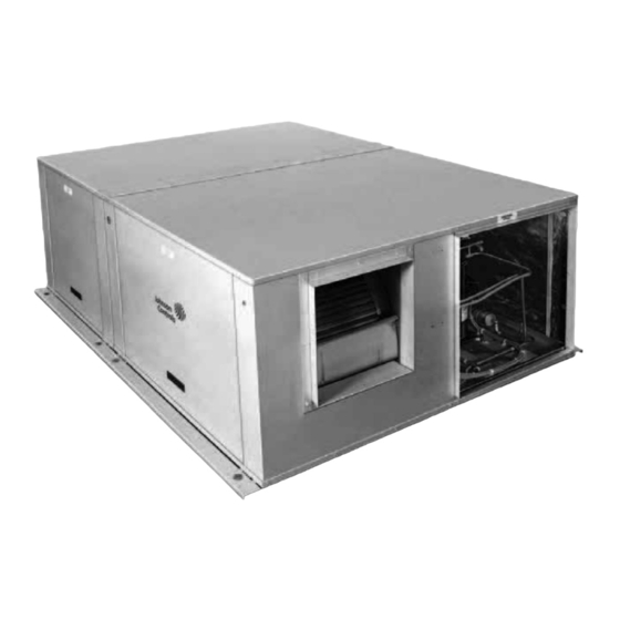
DEQ/DEX ECM Direct Drive Blower Motor With Terminal Block Slide-Out Blower Assembly DEZ 5-Speed Direct Drive Blower Motor With Long-Lasting Slide-Out Blower Assembly Powder Paint Finish High-Efficiency Compressor Heavy Gauge Rigidly Mounted Removable Base Rails Figure 2: Component Location Johnson Controls Unitary Products... -
Page 4: Location
Refer to Table 10 for the clearances required for Unit must be installed on a level roof curb or appropriate construction, servicing and proper unit operation. Johnson Controls Unitary Products... -
Page 5: Ton
Table 4: DEQ 4 Point Load Weight Model Weight (lbs.) Center of Gravity 4 Point Load Location (lbs.) (Tons) Shipping Operating DEQ024 22.25 (2.0) DEQ030 22.25 (2.5) DEQ036 22.25 (3.0) DEQ042 22.25 (3.5) DEQ048 22.25 (4.0) DEQ060 22.25 (5.0) Johnson Controls Unitary Products... -
Page 6: Dex 4 Point Load Weight
Table 7: DEZ Unit Dimensions Front Table 8: DEQ Unit Dimensions Front Dimensions Dimensions Unit Model Unit Model “A” “A” DEZ 024, 030, 036, 042 33-1/2 DEQ 024, 030, 036 33-1/2 DEZ 048, 060 41-1/2 DEQ 042, 048, 060 41-1/2 Johnson Controls Unitary Products... -
Page 7: Dex Unit Dimensions Front
FRONT LOW VOLTAGE CONN. 7/8" DIA. KNOCKOUT HIGH VOLTAGE CONN. 1-31/32" x 7/8" KNOCKOUT CONDENSATE DRAIN 3/4" NPTF 40-1/2 26-3/4 22-1/2 43-1/2 Figure 5: DEX/DEQ/DEX Dimensions Front and Bottom Johnson Controls Unitary Products... -
Page 8: Dex/Deq/Dex Dimensions Back And Bottom
17-1/2" x 16-3/4" 42-3/4 45-1/8 40-3/4 17-5/8 17-1/4 43-1/4 OPENING FOR 3-1/2 RETURN AIR DUCT OPENING FOR SUPPLY AIR DUCT RECOMMENDED DUCT SIZE 17-1/8" x 21-1/2" Figure 7: DEX/DEQ/DEX Roof Curb 1. 8” Roof Curb also available. Johnson Controls Unitary Products... -
Page 9: Ductwork
A fused disconnect switch should be field provided for the unit. Use a sealing compound on male pipe threads. Install the If any of the wire supplied with the unit must be replaced, condensate drain line (3/4” NPTF) to spill into an open drain. Johnson Controls Unitary Products... -
Page 10: Dez/Deq Typical Field Control Wiring Diagram
** = Minimum wire size of 18 AWG wire should be used for all field JUMPER NEEDED FOR FULL SPEED installed 24 volt wire. COMPRESSOR OPERATION 24 VOLT TRANSFORMER PROGRAMMABLE THERMOSTAT ONLY Figure 9: DEX Typical Field Control Wiring Diagram Single Stage Thermostat Johnson Controls Unitary Products... -
Page 11: Dex Typical Field Control Wiring Diagram Two Stage Thermostat
24 volt wire. 24 VOLT TRANSFORMER PROGRAMMABLE THERMOSTAT ONLY Figure 10: DEX Typical Field Control Wiring Diagram Two Stage Thermostat Figure 11: DEZ/DEQ/DEX Typical Field Power Wiring Diagram Johnson Controls Unitary Products... -
Page 12: Dez Electrical Data
24.5 460-3-60 2NH04501546 32.1 2NH04502046 24.1 39.6 2NH04502546 30.1 47.1 1. Minimum Circuit Ampacity. 2. Maximum Over Current Protection per standard UL 1995. 3. Fuse or HACR circuit breaker size installed at factory or field installed. Johnson Controls Unitary Products... -
Page 13: Deq Electrical Data
20.8 460-3-60 2NH04501546 28.3 2NH04502046 24.1 35.8 2NH04502546 30.1 43.3 1. Minimum Circuit Ampacity. 2. Maximum Over Current Protection per standard UL 1995. 3. Fuse or HACR circuit breaker size installed at factory or field installed. Johnson Controls Unitary Products... -
Page 14: Dex Electrical Data
23.5 460-3-60 2NH04501546 31.1 2NH04502046 24.1 38.6 2NH04502546 30.1 46.1 1. Minimum Circuit Ampacity. 2. Maximum Over Current Protection per standard UL 1995. 3. Fuse or HACR circuit breaker size installed at factory or field installed. Johnson Controls Unitary Products... -
Page 15: Dez Physical Data
2 - 22 x 14 x 1 2 - 22 x 14 x 1 2 - 22 x 14 x 1 2 - 22 x 14 x 1 2 - 22 x 14 x 1 2 - 22 x 14 x 1 Johnson Controls Unitary Products... -
Page 16: Deq Physical Data
2 - 22 x 14 x 1 2 - 22 x 14 x 1 2 - 22 x 14 x 1 2 - 22 x 14 x 1 2 - 22 x 14 x 1 2 - 22 x 14 x 1 Johnson Controls Unitary Products... -
Page 17: Dex Physical Data
Quantity - Size 2 - 22 x 14 x 1 2 - 22 x 14 x 1 2 - 22 x 14 x 1 2 - 22 x 14 x 1 2 - 22 x 14 x 1 Johnson Controls Unitary Products... -
Page 18: Compressors
POE (polyolester) compressor lubricants are known to cause long term damage to some synthetic roofing materials. Scroll compressors require proper rotation to operate properly. Failure to check and correct rotation may result in property damage. Johnson Controls Unitary Products... -
Page 19: Airflow Performance
Medium (3) 1854 1783 1020 1703 1065 1605 1104 1528 1146 (5.0) Medium/High (4) 2120 1073 2021 1102 1908 1127 1769 1148 1567 1154 High (5) 2214 1104 2089 1121 1949 1136 1785 1148 1576 1154 Johnson Controls Unitary Products... -
Page 20: Deq Side Duct Application
(4.0) HEAT-A 1600 HEAT-B 1440 Heat HEAT-C 1760 HEAT-D 1600 COOL-A 1500 COOL-B 1650 Cool COOL-C 1800 1030 DEQ060 COOL-D 1900 1013 1072 (5.0) HEAT-A 1900 HEAT-B 1975 Heat HEAT-C 2150 1079 1154 HEAT-D 2070 1066 Johnson Controls Unitary Products... -
Page 21: Deq Bottom Duct Application
(4.0) HEAT-A 1600 HEAT-B 1440 Heat HEAT-C 1760 HEAT-D 1600 COOL-A 1500 COOL-B 1650 Cool COOL-C 1800 1030 DEQ060 COOL-D 1900 1013 1072 (5.0) HEAT-A 1900 HEAT-B 1975 Heat HEAT-C 2150 1079 1154 HEAT-D 2070 1066 Johnson Controls Unitary Products... -
Page 22: Dex Side Duct Application
Heat HEAT-C 1350 HEAT-D 1225 COOL-A 1050 COOL-B COOL-C COOL-D 1120 Cool Y1+Y2 COOL-A 1600 DEX048 Y1+Y2 COOL-B 1400 High (4.0) Y1+Y2 COOL-C 1500 Y1+Y2 COOL-D 1700 HEAT-A 1600 HEAT-B 1440 Heat HEAT-C 1760 HEAT-D 1600 Johnson Controls Unitary Products... -
Page 23: Dex Bottom Duct Application
Heat HEAT-C 1350 HEAT-D 1225 COOL-A 1050 COOL-B COOL-C COOL-D 1120 Cool Y1+Y2 COOL-A 1600 Y1+Y2 COOL-B 1400 DEX048 High (4.0) Y1+Y2 COOL-C 1500 Y1+Y2 COOL-D 1700 HEAT-A 1600 HEAT-B 1440 Heat HEAT-C 1760 HEAT-D 1600 Johnson Controls Unitary Products... -
Page 24: Dez/Deq Additional Static Resistance
1. The pressure drop through the economizer is greater for 100% outdoor air than for 100% return air. If the resistance of the return air duct is less than 0.25 IWG, the unit will deliver less CFM during full economizer operation. Johnson Controls Unitary Products... -
Page 25: Dex Additional Static Resistance
1. The pressure drop through the economizer is greater for 100% outdoor air than for 100% return air. If the resistance of the return air duct is less than 0.25 IWG, the unit will deliver less CFM during full economizer operation. Johnson Controls Unitary Products... -
Page 26: Dez Coil Delta P Vs. Airflow
DEZ Coil Delta P vs’ Airflow 0.35 3.0 - 3.5 Ton 4.0 - 5.0 Ton 0.25 0.15 2.0 - 2.5 Ton 0.05 1000 1200 1400 1600 1800 2000 Airflow (CFM) FIGURE 12:DEZ Coil Delta P vs. Airflow Johnson Controls Unitary Products... -
Page 27: Dez Electric Heat Minimum Supply Air
1070 1070 208/230-1-60 1225 1225 1225 1225 DEX042 208/230-3-60 1225 1225 1225 1225 (3.5) 460-3-60 1225 1225 1225 1225 208/230-1-60 1200 1430 1430 1430 DEX048 208/230-3-60 1200 1430 1430 1430 (4.0) 460-3-60 1200 1430 1430 1430 Johnson Controls Unitary Products... -
Page 28: Dez/Deq/Dex
28.6 10.2 12.3 14.4 16.5 18.6 20.7 22.8 24.1 25.5 26.1 26.8 10.3 12.8 15.2 17.7 20.1 21.7 23.4 24.2 25.0 10.3 12.3 14.3 17.2 20.1 21.6 23.0 12.7 16.8 18.9 21.0 12.6 14.2 15.8 10.6 Johnson Controls Unitary Products... -
Page 29: Dez036 Superheat Charging Table
12.1 13.9 15.8 17.6 18.4 19.2 19.6 20.0 11.0 12.1 13.2 14.3 15.4 16.5 17.6 18.2 18.7 10.9 11.3 11.7 12.1 12.4 12.8 13.2 14.6 16.0 16.7 17.4 11.6 13.3 14.1 15.0 10.6 11.6 12.5 10.1 Johnson Controls Unitary Products... -
Page 30: Deq024 Superheat Charging Table
19.8 20.3 11.3 12.0 12.7 13.4 14.0 14.7 15.4 16.6 17.7 18.3 18.9 10.3 11.0 11.7 12.4 13.1 14.4 15.7 16.4 17.1 10.1 10.8 12.3 13.8 14.5 15.2 10.3 12.0 12.9 13.8 10.3 11.4 12.4 11.0 Johnson Controls Unitary Products... -
Page 31: Deq024 Superheat Charging Table
19.8 20.3 11.3 12.0 12.7 13.4 14.0 14.7 15.4 16.6 17.7 18.3 18.9 10.3 11.0 11.7 12.4 13.1 14.4 15.7 16.4 17.1 10.1 10.8 12.3 13.8 14.5 15.2 10.3 12.0 12.9 13.8 10.3 11.4 12.4 11.0 Johnson Controls Unitary Products... -
Page 32: Deq048 Charging Table
14.7 300 Cfm/Ton 16.9 80/72 19.1 14.5 300 Cfm/Ton 16.4 75/63 18.8 14.5 400 Cfm/Ton 16.4 80/62 18.7 14.7 400 Cfm/Ton 16.6 80/67 19.0 15.0 400 Cfm/Ton 16.9 80/72 19.2 14.5 400 Cfm/Ton 16.4 75/63 18.7 Johnson Controls Unitary Products... -
Page 33: Dex024 Superheat Charging Table
11.4 12.4 12.9 13.4 10.1 10.3 10.4 10.6 10.7 10.9 12.0 13.1 13.6 14.1 10.5 10.7 10.8 10.9 11.1 11.2 11.4 12.5 13.7 14.3 14.9 11.1 11.2 11.3 11.4 11.6 11.7 11.8 13.1 14.4 15.0 15.6 Johnson Controls Unitary Products... -
Page 34: Dez Operation
“B”. Airflow may be decreased by 10% by moving the “ADJ” energize relay ”K2" on the fan control board, and the first jumper to “C”. stage of electric heat will be energized. The indoor blower will operate as indicated in step 1. Johnson Controls Unitary Products... -
Page 35: Deq Operation
75% of the rated airflow. If the fan switch on the only when there is a call for cooling by the thermostat. thermostat is in the "AUTO" position, the blower operates only when there is a call for cooling by the thermostat. Johnson Controls Unitary Products... -
Page 36: Heating Sequence Of Operations
HEATER BANK 2 (HTR 2 & HTR 3) 10 SECOND DELAY ON HEATER BANK 2 (HTR 2 & HTR 3) INSTANT OFF HEATER BANK 1 (HTR 1) ½ SECOND DELAY OFF FAN 10 SECOND DELAY OFF Johnson Controls Unitary Products... -
Page 37: Dez Thermostat Signals (Three Phase Units)
HEATER BANK 3 ELEC. HEAT 20 SEC. DELAY ON HEATER BANK 3 ELEC. HEAT INSTANT OFF HEATER BANK 2 ELEC. HEAT 1/2 SEC. DELAY OFF HEATER BANK 1 ELEC. HEAT 1 SEC. DELAY OFF BLOWER 60 SEC. DELAY OFF Johnson Controls Unitary Products... -
Page 38: Deq Thermostat Signals (Three Phase Units)
HEATER BANK 3 ELEC. HEAT 20 SEC. DELAY ON HEATER BANK 3 ELEC. HEAT INSTANT OFF HEATER BANK 2 ELEC. HEAT 1/2 SEC. DELAY OFF HEATER BANK 1 ELEC. HEAT 1 SEC. DELAY OFF BLOWER 60 SEC. DELAY OFF Johnson Controls Unitary Products... -
Page 39: Maintenance
The wire number or color and terminal designations referred to may vary. Check the wiring label inside the control box access panel for the correct wiring. Johnson Controls Unitary Products... -
Page 40: Typical Wiring Diagrams
1030493-UIM-D-0314 Typical Wiring Diagrams Typical DEZ024-042 Cooling Unit 208/230-1-60 volt Wiring Diagram Johnson Controls Unitary Products... - Page 41 1030493-UIM-D-0314 Typical DEZ048 Cooling Only 208/230-1-60 Volt Wiring Diagram Johnson Controls Unitary Products...
- Page 42 1030493-UIM-D-0314 Typical DEZ060 Cooling Only 208/230-1-60 Volt Wiring Diagram Johnson Controls Unitary Products...
- Page 43 1030493-UIM-D-0314 Typical DEZ036-060 Cooling Unit 230-3-60 volt Wiring Diagram Johnson Controls Unitary Products...
- Page 44 1030493-UIM-D-0314 Typical DEZ036-060 Cooling Unit 460-3-60 volt Wiring Diagram Johnson Controls Unitary Products...
- Page 45 1030493-UIM-D-0314 Typical DEQ024-048 Cooling Only 208/230-1-60 volt Wiring Diagram Johnson Controls Unitary Products...
- Page 46 1030493-UIM-D-0314 Typical DEQ060 Cooling Only 208/230-1-60 volt Wiring Diagram Johnson Controls Unitary Products...
- Page 47 1030493-UIM-D-0314 Typical DEQ036-048 Cooling Only 208/230-3-60 volt Wiring Diagram Johnson Controls Unitary Products...
- Page 48 1030493-UIM-D-0314 Typical DEQ060 Cooling Only 208/230-3-60 volt Wiring Diagram Johnson Controls Unitary Products...
- Page 49 1030493-UIM-D-0314 Typical DEQ036-048 Cooling Only 460-3-60 volt Wiring Diagram Johnson Controls Unitary Products...
- Page 50 1030493-UIM-D-0314 Typical DEQ060 Cooling Only 460-3-60 volt Wiring Diagram Johnson Controls Unitary Products...
- Page 51 1030493-UIM-D-0314 Typical DEX024-048 Cooling Only 208/230-1-60 volt Wiring Diagram Johnson Controls Unitary Products...
- Page 52 1030493-UIM-D-0314 Typical DEX036-048 Cooling Only 208/230-3-60 volt Wiring Diagram Johnson Controls Unitary Products...
- Page 53 1030493-UIM-D-0314 Typical DEX036-048 Cooling Only 460-3-60 volt Wiring Diagram Johnson Controls Unitary Products...
-
Page 54: Start-Up Sheet
Outside air dry bulb temperature Return static (inches of water column) Return air dry bulb temperature Return air wet bulb temperature Total external static pressure Temperature drop Supply air wet bulb temperature Page 1 of 2 Johnson Controls Unitary Products... - Page 55 Provide owner with the owner's manual Explain operation of system to equipment owner Explain thermostat use and programming (if applicable) to owner Explain the importance of regular filter replacement and equipment maintenance Comments and Additional Job Details Page 2 of 2 Johnson Controls Unitary Products...
-
Page 56: 410A Quick Reference Guide
Figure 14: R-410A Quick Reference Guide Subject to change without notice. Printed in U.S.A. 1030493-UIM-D-0314 Copyright © 2014 by Johnson Controls, Inc. All rights reserved. Supersedes: 1030493-UIM-C-0214 York International Corporation 5005 York Drive Norman, OK 73069...
Need help?
Do you have a question about the DEZ Series and is the answer not in the manual?
Questions and answers