Table of Contents
Advertisement
Quick Links
Advertisement
Table of Contents

Related Manuals for Flybox EngiMaster


Summary of Contents for Flybox EngiMaster
- Page 1 ® EngiMaster Engine Information System User Manual...
- Page 2 ® FLYBOX User Manual, Safety Instructions and Warning Booklet This product is not TSO’d and cannot be installed into traditional FAA Part 23 and similarly Type- Certificate Aircraft Document U2023ENGMST Revision#1.0, 11/2023 For firmware version 1.13 This booklet is suitable for printing in A5 format.
- Page 3 ® FLYBOX SECTIONS IMPORTANT NOTICE AND WARNINGS INDEX INTRODUCTION INSTRUMENTS CONFIGURATION OPERATING INSTRUCTIONS TECHNICAL SPECIFICATIONS WARRANTY DISCLAIMER EngiMaster User Manual, Safety Instructions and Warning Booklet REV 1.0...
- Page 4 WARNING: Used to indicate a dangerous situation that can cause personal injury or death if the instruction is disregarded. FAILURE TO DO SO MAY RESULT IN SERIOUS INJURY OR DEATH. EngiMaster User Manual, Safety Instructions and Warning Booklet REV 1.0...
- Page 5 Therefore, we strongly suggest to double check all of the electronic instruments available on the aircraft and to turn them on to verify they function correctly. EngiMaster User Manual, Safety Instructions and Warning Booklet REV 1.0...
- Page 6 WARNING: Installation configuration this instrument should only be carried out by trained and authorised professionals. See the Flyboxavionics website for a list of authorised installers. EngiMaster User Manual, Safety Instructions and Warning Booklet REV 1.0...
- Page 7 Installation and user Manual, Safety Instructions and Warning Booklet, do not install this instrument in his aircraft. NOTE: Flybox Avionics reserves the right to change or improve its products as well as terms, conditions, and notices under which their products are offered without prior notice.
-
Page 8: Table Of Contents
1.3.3.8 - EGT ...............36 1.3.3.9 - Fuel pressure ..........39 1.3.3.10 - Fuel levels ...........41 1.3.3.11 - Fuel computer ..........50 1.3.3.12 - Volt ..............57 1.3.3.13 - Ampere ............59 1.3.3.14 - IAT ...............60 EngiMaster User Manual, Safety Instructions and Warning Booklet REV 1.0... - Page 9 1.3.6 - Firmware upgrade ..........68 1.3.7 - Backup & Restore ..........70 1.3.8 - Fuel Computer Activation ........71 2.0 - Using EngiMaster ............73 2.1 - Page 1: Engine main data ..........74 2.2 - Page 2: Timers ...............79 2.3 - Page 3: Fuel Computer ..........81 2.4 - Page 4: Cameras ............84...
-
Page 10: Primary Action After Installation
40 liters and the EngiMaster indicate as remaining quantity 10.0 liter, you know that to fill the tank you must put approximately 30 liters. Of course keeping in mind that in ground the indications will be different that in flight because of the flight's attitude. - Page 11 BEFORE rely on informations provided by the fuel computer section you must: • Verify that the K-factor set in the EngiMaster is pertinent to the installed fuel flow transducer (for the FT-60 Recube Flybox cod. 503030 is 68000).
-
Page 12: Panel Indicators And Commands
Introduction 1.2 - Panel indicators and commands Pushbuttons are used to switch between different screens and navigate menus. When inside a menu, the meaning of the pushbuttons is always indicated. EngiMaster User Manual, Safety Instructions and Warning Booklet REV 1.0... -
Page 13: Instrument Configuration
® FLYBOX Instrument configuration 1.3 - Instrument configuration Before using the EngiMaster you need to configure it; read completely this chapter and follow step by step the sections to completely configure all the sensors, alarms and preferences available. 1.3.1 - Entering & Browsing the menus To enter the main menu press and hold the F1 and F4 buttons for 3 seconds. - Page 14 CONFIRM (F4). • To return the value to the initial value, press ESC (F1) This way of working is the same for editing all parameters inside the various menus. EngiMaster User Manual, Safety Instructions and Warning Booklet REV 1.0...
-
Page 15: Common Items Description
YES or NO (default YES). • Aural enable: if set to YES it plays an aural warning if EngiMaster audio line out is connected to an intercom. Can be YES or NO (default YES). • Aural repeat: set how many times the aural message must be repeated. - Page 16 Instrument configuration • Output: you can choose to enable one of the two outputs available on EngiMaster when the alarm is activated, useful for example to turn on an alarm light on the cockpit. Set to zero to disable this function (default 0).
-
Page 17: Main Menu
1 and 19 (default 19). • Instruments: enter the “Instruments” menu. • Configuration: enter the “Configuration” menu. • Datalogger: start the Datalogger Viewer functionality. • Peaks Log: start the Peaks Log Viewer functionality. EngiMaster User Manual, Safety Instructions and Warning Booklet REV 1.0... -
Page 18: Instruments Menu
NOTE: Depending on the choice made on the aircraft type, some menu items may or may not be displayed ( i.e. Rotor is not shown if the aircraft type is fixed wing). EngiMaster User Manual, Safety Instructions and Warning Booklet... -
Page 19: Engine Rpm
ECU. It has a range from 1 to 200 (default 1) • Trigger: set the electrical threshold for the RPM input. The number on the right is the actual reading of the EngiMaster User Manual, Safety Instructions and Warning Booklet REV 1.0... - Page 20 RPM meets or exceeds this parameter for 30 seconds). It has a range from 0-6000 (default 4000). Thresholds Assigns the outer limits of the indicator and the ranges of the various thresholds (example yellow range, red range). EngiMaster User Manual, Safety Instructions and Warning Booklet REV 1.0...
- Page 21 Output: as in chapter 1.3.1.1 - Common items description • Delay: as in chapter 1.3.1.1 - Common items description Maintenance counter Set a counter to be notified to perform engine maintenance. EngiMaster User Manual, Safety Instructions and Warning Booklet REV 1.0...
-
Page 22: Rotor Rpm
Reset maintenance: resets the counter when the prompt is shown. 1.3.3.2 - Rotor RPM This menu appears only if Aircraft type is Rotorwing • Filter: as in chapter 1.3.1.1 - Common items description EngiMaster User Manual, Safety Instructions and Warning Booklet REV 1.0... - Page 23 (example yellow range, red range). Alarms Configure the measurement checking system to trigger an alarms if the measure exceed the High threshold or drop below the Low threshold EngiMaster User Manual, Safety Instructions and Warning Booklet REV 1.0...
-
Page 24: Map
Delay: as in chapter 1.3.1.1 - Common items description. 1.3.3.3 - MAP • Enable: as in chapter 1.3.1.1 - Common items description. • Filter: as in chapter 1.3.1.1 - Common items description. EngiMaster User Manual, Safety Instructions and Warning Booklet REV 1.0... -
Page 25: Oil Pressure
(example yellow range, red range). 1.3.3.4 - Oil pressure • Enable: as in chapter 1.3.1.1 - Common items description. • Filter: as in chapter 1.3.1.1 - Common items description. EngiMaster User Manual, Safety Instructions and Warning Booklet REV 1.0... - Page 26 Rotax 10bar fullscale Sensor with 4-20mA current 4-20 loop Thresholds Assigns the outer limits of the indicator and the ranges of the various thresholds (example yellow range, red range). EngiMaster User Manual, Safety Instructions and Warning Booklet REV 1.0...
- Page 27 Aural repeat: as in chapter 1.3.1.1 - Common items description • Output: as in chapter 1.3.1.1 - Common items description. • Delay: as in chapter 1.3.1.1 - Common items description. EngiMaster User Manual, Safety Instructions and Warning Booklet REV 1.0...
-
Page 28: Oil Temperature
Enable: as in chapter 1.3.1.1 - Common items description. • Filter: as in chapter 1.3.1.1 - Common items description. • Unit: as in chapter 1.3.1.1 - Common items description. Option available are °C or °F (default °C) EngiMaster User Manual, Safety Instructions and Warning Booklet REV 1.0... - Page 29 (defaut 50°C - 122°F ) Thresholds Assigns the outer limits of the indicator and the ranges of the various thresholds (example yellow range, red range). EngiMaster User Manual, Safety Instructions and Warning Booklet REV 1.0...
- Page 30 Aural repeat: as in chapter 1.3.1.1 - Common items description • Output: as in chapter 1.3.1.1 - Common items description • Delay: as in chapter 1.3.1.1 - Common items description EngiMaster User Manual, Safety Instructions and Warning Booklet REV 1.0...
-
Page 31: Coolant
Option available are °C or °F (default °C) • Type:sets the probe type according to your electrical installation. Options available are: Menu Label Description Thermocouple type Rotax VDO 323-057 VDO (default) 150°C EngiMaster User Manual, Safety Instructions and Warning Booklet REV 1.0... - Page 32 (example yellow range, red range). Alarms Configure the measurement checking system to trigger an alarms if the measure exceed the High threshold or drop below the Low threshold EngiMaster User Manual, Safety Instructions and Warning Booklet REV 1.0...
-
Page 33: Cht
Output: as in chapter 1.3.1.1 - Common items description. • Delay: as in chapter 1.3.1.1 - Common items description. 1.3.3.7 - CHT • Filter: as in chapter 1.3.1.1 - Common items description. EngiMaster User Manual, Safety Instructions and Warning Booklet REV 1.0... - Page 34 (example yellow range, red range). Input Enables or disables the reading of the signale from a specific input. Input may vary from 4 to 6 depending on the chosen Engine Type. EngiMaster User Manual, Safety Instructions and Warning Booklet REV 1.0...
- Page 35 Configure the measurement checking system to trigger an alarms if the measure exceed the High threshold or drop below the Low threshold. • Upper Warning: as in chapter 1.3.1.1 - Common items description. EngiMaster User Manual, Safety Instructions and Warning Booklet REV 1.0...
-
Page 36: Egt
1.3.3.8 - EGT • Filter: as in chapter 1.3.1.1 - Common items description. • Unit: as in chapter 1.3.1.1 - Common items description. Option available are °C or °F (default °C) EngiMaster User Manual, Safety Instructions and Warning Booklet REV 1.0... - Page 37 Input may vary from 4 to 6 depending on the chosen Engine Type. NOTE: Input number are directly associated to the cilynder number. Refer to the engine manufacturer manuals for cylinder numbering. EngiMaster User Manual, Safety Instructions and Warning Booklet REV 1.0...
- Page 38 Aural repeat: as in chapter 1.3.1.1 - Common items description • Output: as in chapter 1.3.1.1 - Common items description • Delay: as in chapter 1.3.1.1 - Common items description EngiMaster User Manual, Safety Instructions and Warning Booklet REV 1.0...
-
Page 39: Fuel Pressure
Unit: as in chapter 1.3.1.1 - Common items description. Option available are bar or psi (default bar) Thresholds Assigns the outer limits of the indicator and the ranges of the various thresholds (example yellow range, red range). EngiMaster User Manual, Safety Instructions and Warning Booklet REV 1.0... - Page 40 Aural repeat: as in chapter 1.3.1.1 - Common items description • Output: as in chapter 1.3.1.1 - Common items description. • Delay: as in chapter 1.3.1.1 - Common items description. EngiMaster User Manual, Safety Instructions and Warning Booklet REV 1.0...
-
Page 41: Fuel Levels
Unit: as in chapter 1.3.1.1 - Common items description. Option available are L or usg (default L) • mV Step: minimum thresold to detect fuel sensor movements (default 20, it is preferable to leave this value unchanged). EngiMaster User Manual, Safety Instructions and Warning Booklet REV 1.0... - Page 42 The menu items are the same for all tanks, so to avoid repetition only one of the three will be explained. • Enable: as in chapter 1.3.1.1 - Common items description. EngiMaster User Manual, Safety Instructions and Warning Booklet REV 1.0...
- Page 43 Range from 0 to 50L (default 0) Alarms Configure the measurement checking system to trigger an alarms if the measure drop below the Reserve value. EngiMaster User Manual, Safety Instructions and Warning Booklet REV 1.0...
- Page 44 Delay: as in chapter 1.3.1.1 - Common items description Calibration NOTE: if no calibrations have been made for this tank, a message indicating that there are no calibration data will appear. EngiMaster User Manual, Safety Instructions and Warning Booklet REV 1.0...
- Page 45 Operation to Step still to perform be performed The fuel q.ty already Electrical added to the output of the tank at this fuel level point of sensor calibration EngiMaster User Manual, Safety Instructions and Warning Booklet REV 1.0...
- Page 46 In the example, the Calibration step value is set to 3 liters Step 2: Now add the fuel indicated in the green field (it’s the same quantity choosen in the Calibration step parameter). EngiMaster User Manual, Safety Instructions and Warning Booklet REV 1.0...
- Page 47 When the tank is filled: press DONE to confirm the last calibration step and then press SAVE to end the calibration. You will be asked for a confirmation. EngiMaster User Manual, Safety Instructions and Warning Booklet REV 1.0...
- Page 48 If one of these conditions occurs during the calibration, EngiMaster notices that the fuel sensor doesn't produce an electrical change and asks the user if fuel is already EngiMaster...
- Page 49 NOTE: Consider that all fuel additions that will not give any sensor movement will not be counted. This calibration procedure is also identical for the Main Tank and Right Tank EngiMaster User Manual, Safety Instructions and Warning Booklet REV 1.0...
-
Page 50: Fuel Computer
Sender (Default) sender connected to the remote module. • Tanks cap: set the total capacity on-board as the sum of all the usable fuel in all tanks. (range 0-150lt, 0-40 gal). EngiMaster User Manual, Safety Instructions and Warning Booklet REV 1.0... - Page 51 3.78 before set K-Factor parameter in the instrument). If you are using the RED-CUBE FT-60 flow sensor Flybox code 503030, make sure the K- factor is 68000. If you are using another kind of Fuel Flow sensor, make sure about his compatibility of the...
- Page 52 4- Fill the tank/s with the exact same level reached in the step#1, accurately measuring the quantity of fuel added in the tank/s. 5- Turn on EngiMaster and select NO REFUEL (even though you have refilled it’s required to select NO REFUEL).
- Page 53 If the indication is very far from reality you can re-calibrate or manually change the K-Factor. Alarms Configure the measurement checking system to trigger alarms for Reserve, Balance, Endurance conditions. EngiMaster User Manual, Safety Instructions and Warning Booklet REV 1.0...
- Page 54 Aural enable: as in chapter 1.3.1.1 - Common items description • Aural repeat: as in chapter 1.3.1.1 - Common items description • Output: as in chapter 1.3.1.1 - Common items description EngiMaster User Manual, Safety Instructions and Warning Booklet REV 1.0...
- Page 55 Balance: set the fuel quantity for the Balance Alarm. Every time the quantity of fuel used equals this value, EngiMaster will activate an alarm showing TANK SWITCH on the display. This function is useful to keep balanced two wing tanks, switching from one to the other after using a certainquantity of fuel (range: 1 to max of Tank capacity, default OFF).
- Page 56 • Output: as in chapter 1.3.1.1 - Common items description NOTE: leaving the value of the items Reserve, Balance, Endurance to OFF, the corresponding alarm will not be activated. EngiMaster User Manual, Safety Instructions and Warning Booklet REV 1.0...
-
Page 57: Volt
• Filter: as in chapter 1.3.1.1 - Common items description. Thresholds Assigns the outer limits of the indicator and the ranges of the various thresholds (example yellow range, red range). EngiMaster User Manual, Safety Instructions and Warning Booklet REV 1.0... - Page 58 Aural repeat: as in chapter 1.3.1.1 - Common items description • Output: as in chapter 1.3.1.1 - Common items description. • Delay: as in chapter 1.3.1.1 - Common items description. EngiMaster User Manual, Safety Instructions and Warning Booklet REV 1.0...
-
Page 59: Ampere
CAUTION: after calibrating the sensor, do not press ENTER on this value again as it would replace the previous one. If this happens it will be necessary to repeat the calibration procedure EngiMaster User Manual, Safety Instructions and Warning Booklet REV 1.0... -
Page 60: Iat
Unit: as in chapter 1.3.1.1 - Common items description. Option available are °C or °F (default °C) Thresholds Assigns the outer limits of the indicator and the ranges of the various thresholds (example yellow range, red range). EngiMaster User Manual, Safety Instructions and Warning Booklet REV 1.0... - Page 61 Aural repeat: as in chapter 1.3.1.1 - Common items description • Output: as in chapter 1.3.1.1 - Common items description • Delay: as in chapter 1.3.1.1 - Common items description EngiMaster User Manual, Safety Instructions and Warning Booklet REV 1.0...
-
Page 62: Oat
Unit: as in chapter 1.3.1.1 - Common items description. Option available are °C or °F (default °C) 1.3.3.16 - Warmup dependendencies Assigns which parameters should affect the logic for the Warmup/Ready indicator. EngiMaster User Manual, Safety Instructions and Warning Booklet REV 1.0... -
Page 63: Configuration
Aircraft: select the type or aircraft. It can be Rotor wing or Fixed-wing (deafult). This settings will affect all the pages of the devices by showing additional information and changing the layout. EngiMaster User Manual, Safety Instructions and Warning Booklet REV 1.0... - Page 64 (from remote module or ECU). Available options are: Menu Label Description Other Engine not listed Rotax 912 (default) Rotax 914 Rotax 912iS Rotax 915iS EngiMaster User Manual, Safety Instructions and Warning Booklet REV 1.0...
-
Page 65: Audio
• Test audio: used to play an aural message. This can be usefull to verify if the connection with the intercom has been properly made. 1.3.4.2 - Serial port EngiMaster User Manual, Safety Instructions and Warning Booklet REV 1.0... -
Page 66: Gps
GPS fix, directly from this screen. • Time zone: this is the only editable value in the submenu and ranges from -12 to +13. Changing it varies the Local Time in real time. EngiMaster User Manual, Safety Instructions and Warning Booklet REV 1.0... -
Page 67: Backlight
Dimmer paramater. Auto need that the external light sensor (cod. 105800) must be installed into EngiMaster. • Delay: assigns the delay time between the detection of the change in ambient light and the start of the change in display brightness. -
Page 68: Firmware Upgrade
This menu is used for upgrading the firmware versions of the EngiMaster and the connected remote module, using a USB 2.0 flash drive. If you have received the upgrade files for the EngiMaster and/or remote module, copy them in the root folder of a USB 2.0 flash drive. - Page 69 Instrument configuration 3. If the files are correctly recognized the upgrade list will populate as in the next image. 4. Select if you want to upgrade the EngiMaster or the Remote module and then push ENTER to start the upgrade.
-
Page 70: Backup & Restore
This menu is used to save or restore all the settings and calibrations of your EngiMaster. Backup: Insert a USB flash drive in the USB rear connector on the EngiMaster and then push ENTER with this item selected to save all the settings on the USB 2.0 flash drive. -
Page 71: Fuel Computer Activation
(Use + or - to increase or decrease the digit, then push NEXT to confirm) 4. If the code is correct the EngiMaster shows on display “Fuel Computer Activated!”. 5. Push on CONFIRM then push on BACK to exit this screen. - Page 72 ® FLYBOX Operating Instructions WRITE DOWN HERE THE ACTIVATION DATA: KEY: NOTE: (1) The serial number can be seen on the label on the back of EngiMaster. EngiMaster User Manual, Safety Instructions and Warning Booklet REV 1.0...
-
Page 73: Using Engimaster
1.3.7 - Fuel Computer Activation. NOTE: in this manual is presented the full version of the pages but your EngiMaster may differ depending on the optionals and sensors installed in your aircraft. EngiMaster User Manual, Safety Instructions and Warning Booklet REV 1.0... -
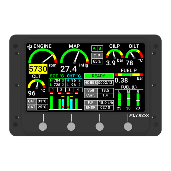
Page 74: Page 1: Engine Main Data
Available parameters are: • Engine rpm: graphical and numerical indication. • MAP: graphical and numerical indication, expressed in inches of mercury. EngiMaster User Manual, Safety Instructions and Warning Booklet REV 1.0... - Page 75 EngiMaster. The indications are approximated, do not solely rely on EngiMaster to determine the fuel available in the tanks but always refer to primary instrument installed in your aircraft.
- Page 76 • Lane status: indicates if the ECU lane are working properly (A or B in green). If one is missing the relative ID became red. This gauge is visible only for electronic injected engine. EngiMaster User Manual, Safety Instructions and Warning Booklet REV 1.0...
- Page 77 • Rotor rpm: graphical and numerical indication. • MAP: graphical and numerical indication, expressed in inches of mercury. • Oil pressure: graphical and numerical indication, expressed in bar or psi depending on user settings. EngiMaster User Manual, Safety Instructions and Warning Booklet REV 1.0...
- Page 78 EngiMaster. The indications are approximated, do not solely rely on EngiMaster to determine the fuel available in the tanks but always refer to primary instrument installed in your aircraft.
-
Page 79: Page 2: Timers
® FLYBOX Operating Instructions measures becomes in its safe zone the indicatorchange state to “READY” in green background, that automatically disappear 30 seconds after take-off. 2.2 - Page 2: Timers EngiMaster User Manual, Safety Instructions and Warning Booklet REV 1.0... - Page 80 RPM) is exceeded for 30 seconds. • ENGINE PEAK: maximum RPM peak reached by the engine during its life. • ROTOR PEAK: maximum rotor peak reached during its life. (Only for rotorcraft) EngiMaster User Manual, Safety Instructions and Warning Booklet REV 1.0...
-
Page 81: Page 3: Fuel Computer
As explained in chapter 1.3.2.11 - Fuel computer. At every startup of the instrument you will be asked if refueling has been done, one the following options must be selected: EngiMaster User Manual, Safety Instructions and Warning Booklet REV 1.0... - Page 82 NOTE: If you need to correct a wrong fuel quantity add, select ADD FUEL and insert a negative value. EngiMaster User Manual, Safety Instructions and Warning Booklet REV 1.0...
- Page 83 (for example when the engine is not running) the display shows “- - - -”. RESERVE: Display the fuel remaining at destination; the destination is intended as the approaching GPS EngiMaster User Manual, Safety Instructions and Warning Booklet REV 1.0...
-
Page 84: Page 4: Cameras
Pressing EXIT will bring back to the last viewed page. NOTE: if instead of the video appears the text NO SIGNAL means that the camera could be off or not connected correctly. EngiMaster User Manual, Safety Instructions and Warning Booklet REV 1.0... -
Page 85: Alarms
® FLYBOX Operating Instructions 3.0 - Alarms EngiMaster continuously monitor all the sensors and when a measurement exceed its setpoint, either the probe/ sensor making the measurement disconnects, the corresponding alarm is activated (if enabled by the user). An alarm condition is indicated in this ways: •... -
Page 86: Datalogger
Use the arrows (F2 and F3 push buttons) to scroll through the list. Then pressing SELECT the chosen flight will become highlighted. EngiMaster User Manual, Safety Instructions and Warning Booklet REV 1.0... - Page 87 VIEW: open the flight in view mode. View mode allows you to view charts of the data recorded in the selected flight. The interface will look like the image below: EngiMaster User Manual, Safety Instructions and Warning Booklet REV 1.0...
- Page 88 NOTE: the date and time indications is read from an external GPS, if connected; if no GPS is connected to the EngiMaster, these indications will not be available. 2. Engine hours: total accumulated engine hourmeter referred to the cursor position (5).
- Page 89 Operating Instructions • ITEM/CURSOR: switch between the scrolling mode The datalogger records all measurements displayed in the EngiMaster screens. The charts displayed therefore depend on what measurements the user has set in the instruments settings. EngiMaster User Manual, Safety Instructions and Warning Booklet...
-
Page 90: Technical Specifications
CAUTION: Avoid any chemical cleaners or solvents that can damage the display anti-reflective coating or plastic components. Do not use cleaners containing ammonia. Do not spray water or cleaner directly onto the display. EngiMaster User Manual, Safety Instructions and Warning Booklet REV 1.0... - Page 91 One Year Warranty: Product support and warranty information can be found at www.flyboxavionics.it. Flybox® warrants this Product to be free from defects in materials and workmanship for 12 months from date of delivery. The inactivity of the Products determined by periods of repair does not involve the extension of the warranty period.
- Page 92 Use of this product is unauthorized in any jurisdiction that does not give effect to all provisions of these terms and conditions, including without limitation this paragraph. EngiMaster User Manual, Safety Instructions and Warning Booklet REV 1.0...
- Page 93 WARNING: All photos, data, drawings, instruments layouts, technical solutions and data representation you find in this document or watching at FLYBOX® instruments working and/or you can access by means of any other media, including web sites, are sole property of MICROEL s.r.l., cannot be copied or imitate without a written permission of MICROEL s.r.l.
- Page 94 ® FLYBOX Page intentionally empty EngiMaster User Manual, Safety Instructions and Warning Booklet REV 1.0...
- Page 95 ® FLYBOX Page intentionally empty EngiMaster User Manual, Safety Instructions and Warning Booklet REV 1.0...
- Page 96 Flybox® is a registred brand of Microel s.r.l.- Italy www.flyboxavionics.it MICROEL s.r.l. Via Mortara 192-194 27038 Robbio (PV) - ITALY Tel +39-0384-670602 - Fax +39-0384-671830 EngiMaster User Manual, Safety Instructions and Warning Booklet REV 1.0...
Need help?
Do you have a question about the EngiMaster and is the answer not in the manual?
Questions and answers