Table of Contents
Advertisement
Quick Links
Advertisement
Table of Contents

Related Manuals for Flybox EngiMaster


Summary of Contents for Flybox EngiMaster
- Page 1 ® ® EngiMaster Engine Information System Installation Manual...
- Page 2 ® FLYBOX Installation Manual, Safety Instructions and Warning Booklet This manual is for Authorized Installers only. This manual is distributed by Microel directly to installers and no part of this manual may be reproduced, copied, transmitted, disseminated, downloaded or stored on any storage medium for any purpose without the prior written consent of Microel.
- Page 3 ® FLYBOX SECTIONS INTRODUCTION IMPORTANT NOTICE AND WARNINGS INDEX SYSTEM OVERVIEW MECHANICAL INSTALLATION ELECTRICAL INSTALLATION SENSORS INSTALLATION AFTER INSTALLATION OPERATIONS TECHNICAL SPECIFICATIONS WARRANTY - WARRANTY ACTIVATION DISCLAIMER EngiMaster Installation Manual, Safety Instructions and Warning Booklet REV 1.0...
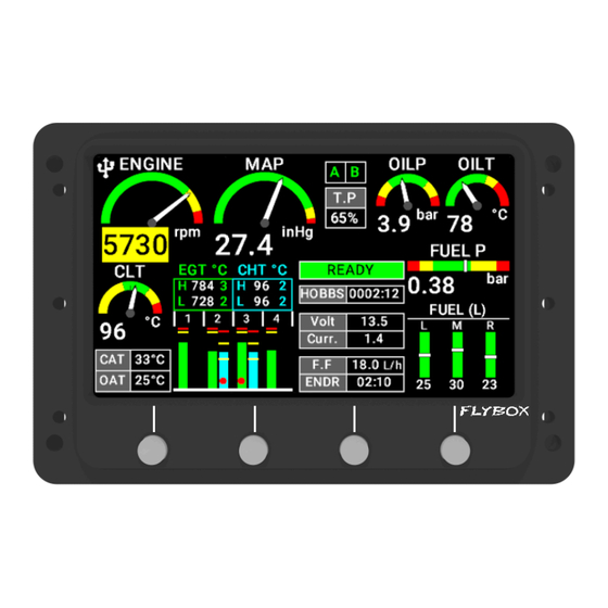
- Page 4 ® FLYBOX Introduction Examples of available screens Engine main data: Airplane Engine main data: Rotorcraft EngiMaster Installation Manual, Safety Instructions and Warning Booklet REV 1.0...
- Page 5 The EngiMaster instrument is available in 2 different models: landscape and portrait mounting. This manual describes the installation of all of the 2 models. Our intention in developing the EngiMaster was to create a product that is light and compact, powerful and easy to use.
- Page 6 WARNING: Used to indicate a dangerous situation that can cause personal injury or death if the instruction is disregarded. FAILURE TO DO SO MAY RESULT IN SERIOUS INJURY OR DEATH. EngiMaster Installation Manual, Safety Instructions and Warning Booklet REV 1.0...
- Page 7 Therefore, we strongly suggest to double check all of the electronic instruments available on the aircraft and to turn them on to verify they function correctly. EngiMaster Installation Manual, Safety Instructions and Warning Booklet REV 1.0...
- Page 8 WARNING: Installation configuration this instrument should only be carried out by trained and authorised professionals. See the Flyboxavionics website for a list of authorised installers. EngiMaster Installation Manual, Safety Instructions and Warning Booklet REV 1.0...
- Page 9 Installation and user Manual, Safety Instructions and Warning Booklet, do not install this instrument in his aircraft. NOTE: Flybox Avionics reserves the right to change or improve its products as well as terms, conditions, and notices under which their products are offered without prior notice.
-
Page 10: Table Of Contents
3.0 Engimaster Mechanical Installation ........16 3.0.1 Panel Cut-Out ............18 3.1 Remote Module Mechanical Installation ......19 4.0 Electrical Installation ............20 4.1 EngiMaster Electrical Installation ....... 24 4.1.1 CN1 22 Pole Connector ........25 4.1.2 CN2 4 Pole Connector ........28 4.1.3 CAN Connector ..........29 4.2 Remote Module Electrical Installation ...... - Page 11 5.11 MAP Connection ............57 5.12 RPM Pickup Input ............. 57 5.13 Rotor RPM Input ............57 5.14 Separable Connections for Thermocouples ..... 58 5.15 Camera Input ............60 6.0 Instrument Use ..............61 EngiMaster Installation Manual, Safety Instructions and Warning Booklet REV 1.0...
-
Page 12: System Overview
System overview 1.0 System Overview CONSTRUCTION FEATURES The EngiMaster front panel is built from solid aluminum alloy, CNC milled and powder coated to last a long time over the years always showing a new appearance. The other parts of the housing are made of corrosion-protected aluminium. - Page 13 EASY DATALOG SAVING Easy logging of the data for debug purpose. If needed, the EngiMaster unit can save a last flight log on the internal memory, easely exportable to an USB pen drive. The user can then send the log via e-mail to the installer for a help/ support request.
-
Page 14: Panel Indicators & Commands
® FLYBOX System overview 2.0 Panel Indicators & Commands High Brightness Color Display Pushbuttons EngiMaster Installation Manual, Safety Instructions and Warning Booklet REV 1.0... - Page 15 ® FLYBOX System overview Integrated MAP Input EngiMaster Installation Manual, Safety Instructions and Warning Booklet REV 1.0...
-
Page 16: Engimaster Mechanical Installation
® FLYBOX Mechanical Installation 3.0 EngiMaster Mechanical Installation It's recommended to choose a position that permits optimal display visibility. The instrument Is supplied with four M4X10mm screws to install it to the panel, if you use other screws consider that the maximum thread length inside the instrument body is 10mm. - Page 17 ® FLYBOX Mechanical Installation EngiMaster Installation Manual, Safety Instructions and Warning Booklet REV 1.0...
-
Page 18: Panel Cut-Out
® FLYBOX Mechanical Installation 3.0.1 Panel Cut-Out Scale 1:1 EngiMaster Installation Manual, Safety Instructions and Warning Booklet REV 1.0... -
Page 19: Remote Module Mechanical Installation
M4 screws. The max length of the CAN-bus that connects the remote module to the EngiMaster is 20 meters. When choosing a location where to install the remote module, consider that the operating temperature range is -20~+70°C. -
Page 20: Electrical Installation
CAUTION: Voltage peaks on the supply line that exceeds the operating limits can damage the device. General wiring hints: ● It is recommended that EngiMaster and remote module be installed prior to constructing the wiring harnesses and cables. ● Use aeronautic cable for the wiring. - Page 21 EngiMaster. Contacts for the connectors must be crimped onto the individual wire of the wiring harness. CAUTION: To avoid damage to the EngiMaster/Remote module, take precautions to prevent Electro-Static Discharge (ESD)
- Page 22 Each end must be terminated with a 120 ohm resistor, that in the case of EngiMaster and remote module is integrated inside the instruments so that the installer should simply connect together two pin on the connector to perform the required terminations.
- Page 23 CAN bus share the same power ground reference. This means that the power ground of the various devices must be connected to a single ground point (do not use aircraft structure as a power ground). EngiMaster Installation Manual, Safety Instructions and Warning Booklet REV 1.0...
-
Page 24: Engimaster Electrical Installation
Molex P/N 43025-0400 (4 pole housing) Molex P/N 43025-2200 (22 pole housing) Molex P/N 43030-0001 (female crimp terminal) The terminals can be crimped with: - Flybox Professional Crimping Tool cod. 603000 - Molex tool P/N 63819-0000 EngiMaster Installation Manual, Safety Instructions and Warning Booklet... -
Page 25: Cn1 22 Pole Connector
Max 300mA Out NPN open collector Out 1 (Not protected) Max 300mA Out NPN open collector Out 2 (Not protected) External switch 1 In Ambient ligh sensor input GND Main supply EngiMaster Installation Manual, Safety Instructions and Warning Booklet REV 1.0... - Page 26 Main Unit Signals explanation ● Power supply (PIN#11): The EngiMaster is capable of operating at either 14 or 28 VDC, AWG22 wire is enough. It’s recommended to insert a 2A circuit breaker on the positive wire that supply both EngiMaster and remote module.
- Page 27 ® FLYBOX Electrical installation Main Unit CN1 Wiring Connections EngiMaster Installation Manual, Safety Instructions and Warning Booklet REV 1.0...
-
Page 28: Cn2 4 Pole Connector
4.1.2 CN2 4 Pole Connector 4 pin Molex Micro-Fit Receptacle P/N 43025-0400. View from wires insertion side. PIN # Type Description Video Input 2 Video Input 3 Video Input 1 CN2 Wiring Connections EngiMaster Installation Manual, Safety Instructions and Warning Booklet REV 1.0... -
Page 29: Can Connector
CAN 2 H Internally connected with the Pin 1 - CAN 2 H (Lower connector) CAN 2 L Internally connected with the Pin 2 - CAN 2 L (Lower connector) EngiMaster Installation Manual, Safety Instructions and Warning Booklet REV 1.0... - Page 30 CAN 2 or both, as indicated in the table. Connecting both CAN 1 and CAN 2 lines ensures that engine measurements are read in case one of the two CAN lines is disconnected. EngiMaster Installation Manual, Safety Instructions and Warning Booklet REV 1.0...
-
Page 31: Remote Module Electrical Installation
Molex P/N 43025-2200 (22 pole housing) Molex P/N 43025-2400 (24 pole housing) Molex P/N 43030-0001 (female crimp terminal) The terminals can be crimped with: - Flybox Professional Crimping Tool cod. 603000 - Molex tool P/N 63819-0000 EngiMaster Installation Manual, Safety Instructions and Warning Booklet... -
Page 32: Cn1 16 Pole Connector
16000. View from wires insertion side. PIN # Type Description Note Flybox bus termination Flybox bus H signal for EngiMaster connection Not Used / Reserved Not Used / Reserved RPM signal Input Not Used / Reserved Not Used / Reserved... - Page 33 ● FLYBOX BUS (PIN#1-2-9-10): This bus is used exclusively for communication with EngiMaster; use shielded or twisted wire pair, AWG24 is enough. Max length of this bus is 20 meters. The Flybox bus termination (jump wire pin#1 with pin#9) is required.
- Page 34 NOTE 2: This rotor tachometer input support push-pull type sensors with 0- 12volt output. It’s possible also to use open-collector type sensors but it’s required to connect a 10 Kohm pull-up resistor between this signal and +12V. EngiMaster Installation Manual, Safety Instructions and Warning Booklet...
-
Page 35: Cn2 24 Pole Connector
J (+) / Coolant temperature sensor CHT5 sensor input: Rotax, PT1000 or thermocouple J (+) CHT4 sensor input: Rotax, PT1000 or thermocouple J (+) CHT3 sensor input: Rotax, PT1000 or thermocouple J (+) EngiMaster Installation Manual, Safety Instructions and Warning Booklet REV 1.0... - Page 36 ● EGT negative inputs (PIN#7-8-9-10-11-12): Connect to these pins the negative wire of the thermocouples. ● EGT positive inputs (PIN#19-20-21-22-23-24): Connect to these pins the positive wire of the thermocouples. EngiMaster Installation Manual, Safety Instructions and Warning Booklet REV 1.0...
- Page 37 ® FLYBOX Electrical installation Remote Module CN2 Wiring Connections EngiMaster Installation Manual, Safety Instructions and Warning Booklet REV 1.0...
-
Page 38: Cn3 22 Pole Connector
Right tank fuel level Res: max 300 OHM; sensor input Volt:0~5 V Res: max 10 KOHM; Volt:0~5 V ; Oil pressure sensor input Amp: min 4 max 20 mA (internal 200 ohm) EngiMaster Installation Manual, Safety Instructions and Warning Booklet REV 1.0... - Page 39 ● Jumper wire for oil pressure selection (PIN#6-17): If you use 4-20mA type oil pressure sensor (Rotax 956413 or Flybox 602000) connect pin6 with pin17 with a jumper wire. If you use VDO type oil pressure sensor (Rotax 956415) leave unconnected both pin6 and pin17.
- Page 40 ● CAT - Carburetor/Airbox temperature (PIN#9): Support PT1000 sensors. See chap.5.6 for further details. ● Current sensor signal input (PIN#19): Support Flybox 601060 sensor. See chap.5.7 for further details. ● Fuel pressure sensor input (PIN#20): Support Flybox 601041 sensor. See chap.5.10 for further details.
- Page 41 ® FLYBOX Electrical installation Remote Module CN3 Wiring Connections EngiMaster Installation Manual, Safety Instructions and Warning Booklet REV 1.0...
-
Page 42: Sensors Installation
Errors in the measurements are usually caused by points in the aircraft where there is insufficient grounding. EngiMaster Installation Manual, Safety Instructions and Warning Booklet REV 1.0... -
Page 43: Cht Sensors
No additional sensors are required: with Rotax 912iS the coolant temperature is measured by the ECU and sent, using the CAN bus connection, to the EngiMaster. Only if you need to install additional coolant or cylinder head temperature sensors you can use the free inputs CHT2-CHT3-CHT4. -
Page 44: Egt Sensors
#7 to #12 (EGT6 to EGT1). 5.2.1 Flybox® EGT thermocouples Flybox ® EGT thermocouples are K-type; positive wire is RED, negative is GREEN. INSTALLATION NOTES: 1. Drill a 6 mm diameter hole in the exhaust manifold (at the position indicated by the engine's manufacturer) and weld the furnished probe coupling. - Page 45 ® FLYBOX Sensors installation EngiMaster Installation Manual, Safety Instructions and Warning Booklet REV 1.0...
-
Page 46: Oil Temp. Sensor
Connect red wire to pin#11 of CN3 remote module connector; connect white wire to pin#16. Connect pin#6 to pin#17 of CN3 remote module connector. ● Flybox ® P/N 602000 Compatible with the Rotax 4-20mA sensors. Connect brown wire to pin#11 of CN3 remote module connector;... -
Page 47: Outside Air Temperature Sensor (Oat)
● Flybox ® OAT sensor (P/N 601020) Flybox ® OAT sensor is a PT1000 and can be fixed with a 5 mm countersunk screw. For optimal outside temperature indication it must not be installed in direct sunlight locations or near heat sources. -
Page 48: Airbox/Carburetor Temperature Sensor (Cat)
Connect one wire to pin #9 of CN3 remote module connector and the other wire to aircraft ground. ● Flybox ® CAT sensor (P/N 601030) Flybox ® CAT sensor is a PT1000 with a M10x1 thread. EngiMaster Installation Manual, Safety Instructions and Warning Booklet... -
Page 49: Current Sensor
FLYBOX Sensors installation 5.7 Current Sensor The current sensor supplied by Flybox ® (P/N 601060) is able to measure current between -50 and +50 Amperes. It must not be installed between battery and starter circuit because of the high current flowing into this path. -
Page 50: Current Sensor Connections
The procedure is the following: 1. Connect only the 3 wire from the current sensor to the EngiMaster and leave disconnected the 2 cable “A+” and “A-”. 2. Turn-on the EngiMaster. 3. Go in the MAIN MENU → INSTRUMENTS →... -
Page 51: Fuel Flow Sensor
2 is subtracted from the flow measured by sensor 1 and the resulting amount represents the instantaneous flow of fuel burned. EngiMaster accepts all flow meters as long as they meet the following characteristics: amplitude range: 5 - 30 Vpp frequency range: 2 Hz - 10 Khz min. - Page 52 RPM speed; verify also that at full RPM the fuel pressure after the fuel flow transducer never drop below the minimum pressure indicated in your engine's manual. EngiMaster Installation Manual, Safety Instructions and Warning Booklet REV 1.0...
- Page 53 ® FLYBOX Sensors installation Typical example installation of the fuel flow transducer on carbureted engines: EngiMaster Installation Manual, Safety Instructions and Warning Booklet REV 1.0...
-
Page 54: Fuel Level Sensors
It's also possible to install a mixed type of sensors (i.e. 1 resistive + 1 capacitive). CAUTION: Resistive type fuel level sensors connected to EngiMaster must not be connected to any other instrument. Disconnect any previously used instrument. 5.9.1 Fuel level sensors connections... - Page 55 Another example (fig.2) is if a tank can holds 40 liters of fuel but at 25 liters the fuel is at the top of the sensor, the maximum that the instrument will display is 25 liters. EngiMaster Installation Manual, Safety Instructions and Warning Booklet...
-
Page 56: Fuel Pressure Sensor
Sensors installation 5.10 Fuel Pressure Sensor The fuel pressure transducer+fitting is supplied by Flybox ® (P/N 601041); the electrical connections are: BROWN WIRE: +12V Supply (connect to pin #22 of CN3 remote module connector). GREEN WIRE: GND (connect to pin #21 of CN3 remote module connector). -
Page 57: Map Connection
0-12volt output. It’s possible also to use open- collector type sensors but it’s required to connect a 10 Kohm pull-up resistor between this signal and +12V. It is possible to purchase sensors from Flybox ® with ord. cod.105896. EngiMaster... -
Page 58: Separable Connections For Thermocouples
5.14 Separable Connections for Thermocouples If it is necessary to split the thermocouples connections in separable harnesses, you must use proper cables and connectors, available also from Flybox ® with ord. cod.651012. The connections are the following: EngiMaster Installation Manual, Safety Instructions and Warning Booklet REV 1.0... - Page 59 ® FLYBOX Sensors installation NOTE: Wires' color are referred to Flybox ® supplied thermocouples, other thermocouples may have different colors coding. In case of wrong wiring the temperature indication will not be correct. EngiMaster Installation Manual, Safety Instructions and Warning Booklet...
-
Page 60: Camera Input
The EngiMaster has 3 camera inputs supporting PAL format. Cameras must be powered directly from the battery bus. It is possible to purchase cameras from Flybox ® with ord. cod.601070/601071. NOTE: the instrument does not make video recordings or capture images. -
Page 61: Instrument Use
EngiMaster Installation Manual, Safety Instructions and Warning Booklet REV 1.0... - Page 62 ® FLYBOX Technical specifications Technical specifications ENGIMASTER ● Graphic TFT LCD with backlight and coated glass, 4.3” ● Powder painted aluminium case ● Dimensions: 124.9 x 83.5 x 17.8 mm (body) ● Weight: 200 g ● Supply voltage: 10 ~ 30 V= ●...
- Page 63 ● Fuel pressure from Flybox® transducer ● RPM tachometer input ● Rotor tachometer input for helicopter version ● Oil pressure from Flybox®, ROTAX or JABIRU sensors ● 2 Oil temperature inputs from ROTAX, JABIRU or PT1000 sensors ● Carburetor/Airbox from PT1000 sensor ●...
- Page 64 One Year Warranty: - the product will be covered by warranty ONLY if registered exclusively by filling out the appropriate form on the Flybox website, which can be reached from the instrument page http://www.flyboxavionics.it/login.html. - registration of the product must be carried out by the Installer no later than 10 days from the date of installation.
- Page 65 Use of this product is unauthorized in any jurisdiction that does not give effect to all provisions of these terms and conditions, including without limitation this paragraph. EngiMaster Installation Manual, Safety Instructions and Warning Booklet...
- Page 66 WARNING: All photos, data, drawings, instruments layouts, technical solutions and data representation you find in this document or watching at FLYBOX® instruments working and/or you can access by means of any other media, including web sites, are sole property of MICROEL s.r.l., cannot be copied or imitate without a written permission of MICROEL s.r.l.
- Page 67 ® FLYBOX Page intentionally blank EngiMaster Installation Manual, Safety Instructions and Warning Booklet REV 1.0...
- Page 68 Flybox® is a registred brand of Microel s.r.l.- Italy www.flyboxavionics.it MICROEL s.r.l. Via Mortara 192-194 27038 Robbio (PV) - ITALY Tel +39-0384-670602 - Fax +39-0384-671830 EngiMaster Installation Manual, Safety Instructions and Warning Booklet...
Need help?
Do you have a question about the EngiMaster and is the answer not in the manual?
Questions and answers