
Related Manuals for Flybox Omnia57-80 Series


Summary of Contents for Flybox Omnia57-80 Series
- Page 1 FLYBOX ® ® LIFT Omnia57-80 LIFT Installation and User Manual, (Omnia57-80 family) Safety Instructions and Warning Booklet Rev. 2.0...
- Page 2 Installation and User Manual, Safety Instructions and Warning Booklet This product is not TSO’d and cannot be installed into traditional FAA Part 23 and similarly Type-Certificate Aircraft Document A2021-LIFT Revision#1.0, 11/2021 For firmware version 1.0 This booklet is suitable for printing in A5 format.
- Page 3 SECTIONS INTRODUCTION IMPORTANT NOTICE AND WARNINGS INDEX OMNIA FAMILY SYSTEM OVERVIEW MECHANICAL INSTALLATION ELECTRICAL INSTALLATION INSTRUMENT SETTINGS OPERATING INSTRUCTIONS TECHNICAL SPECIFICATIONS WARRANTY DISCLAIMER...
- Page 4 Examples of available screens...
- Page 5 FLYBOX ® Introduction Thank you for purchasing a Flybox® Omnia instrument. Omnia instruments are available in 2 different formats, both with the same functionality: Omnia57 (2-1/8") and Omnia80 (3-1/8"). This manual describes both formats. Our intent in developing the Omnia instrument family was to create a light and compact product, powerful and easy to install and use.
- Page 6 FLYBOX ® Important notices & warnings Symbols used in the Installation and User Manual, Safety Instructions and Warning Booklet NOTE: Used to highlight important information. CAUTION: Used to warn the user, it indicates a potentially hazardous situation or improper use of the product.
- Page 7 FLYBOX ® Important notices & warnings WARNING: These instructions must be provided to users before use, and retained for ready reference by the user. The user must read, understand (or have explained) and heed all instructions and warnings supplied with this product and with those products intended for use in association with it.
- Page 8 FLYBOX ® Important notices & warnings WARNING: This device is operated through a software which from time to time can be updated and/or subject to change. Please, always refer to the Installation and User Manual, Safety Instructions and Warning Booklet for the last updated version of the software available at www.flyboxavionics.it...
- Page 9 Installation and user Manual, Safety Instructions and Warning Booklet, do not install this instrument in his aircraft. NOTE: Flybox Avionics reserves the right to change or improve its products as well as terms, conditions, and notices under which their products are offered without prior notice.
-
Page 10: Table Of Contents
FLYBOX ® Index INDEX SECTION 1 - Omnia Family System overview…..………… 1.1 - Construction Features …….…………………………..…. 1.2 - Ergonomics………...…...………….……………………. 1.3 - Interconnection Ability ………...…...…………..……….. 1.4 - Easy Software Update ………...…...………….…………. 1.5 - Easy Datalog Saving ………...…...………….…………… 1.6 - Interfaces.. ………...…...………….………………………... - Page 11 FLYBOX ® Index 4.3 - Setup Menu Navigation……….…….…..…….………… 4.4 - Main Setup Menu… ………………………….………… 4.4.1 - Speed Submenu…..……………………….…………… 4.4.2 - Special Submenu.….….…….….…………….….……… 23 4.5 - Backlight Submenu….………….………………………… 26 SECTION 5 - Operating Instructions……….…………………… 29 5.1 - Firmware Upgrade..……………..…..….….…….………. 5.2 - Backup/Restore……………….…..…….………….….….
-
Page 12: Section 1 - Omnia Family System Overview
FLYBOX ® Omnia Family System Overview OMNIA FAMILY SYSTEM OVERVIEW The Omnia57-80 instrument family has many innovative features, common to all models as described below. 1.1 CONSTRUCTION FEATURES Omnia instrument family is built from solid aluminum alloy, CNC milled and powder coated to last a long time over the years always showing a new appearance. -
Page 13: Interconnection Ability
FLYBOX ® Omnia Family System Overview 1.3 INTERCONNECTION ABILITY All the instruments of the Omnia family can be connected together via CAN1 to form a communication network, making some data exchange operations simpler. The software update of a Omnia instrument connected in group takes place through the CAN1 bus communication with the instrument that has the USB pen drive connected. -
Page 14: Easy Software Update
1.4 EASY SOFTWARE UPDATE The user can download any new firmware, when available, from Flybox website, connect a USB pen drive to the instrument and freely update it with the last features. With one USB connection only, it will be possible to update every instrument installed in the panel. -
Page 15: Interfaces
2 separate CAN BUS: CAN1 bus is used to connect the Omnia instruments together, CAN2 bus is used to interface them with other Flybox instruments or with external devices like Engines ECUs or new devices to be developed in the future. -
Page 16: Section 2 - Mechanical Installation
FLYBOX ® Mechanical installation MECHANICAL INSTALLATION It's recommended to choose a position that permits optimal display visibility. The instrument is supplied with four M4 screws to install it to the panel, if you use other screws consider that the maximum thread length inside the instrument body is 10mm (see the picture below). -
Page 17: Omnia57 Mechanical Dimensions
FLYBOX ® Mechanical installation 2.1 OMNIA57 MECHANICAL DIMENSIONS The Omnia57 instrument fits in a standard 2 ¼” (57 mm) panel cutout. CAUTION: The maximum screw length inside the instrument body is 10mm. NOTE: For an installation without interference, consider making a hole of at least 57.5 mm diameter. -
Page 18: Omnia80 Mechanical Dimensions
FLYBOX ® Mechanical installation 2.2 OMNIA80 MECHANICAL DIMENSIONS The Omnia80 instrument fits in a standard 3 1/8” (80 mm) panel cutout. NOTE: For an installation without interference, consider making a hole of at least 80.5 mm diameter. Omnia57-80 LIFT Installation and User Manual, Safety Instructions and Warning Booklet Rev. -
Page 19: Omnia80 Max Screw Lenght
FLYBOX ® Mechanical installation 2.3 OMNIA80 Max screw length The screws supplied (M4x6mm), are suitable for panel thicknesses between 1.5 mm and 2 mm. Flat nylon washers are also supplied with the screws for use with very thin panels. CAUTION: The maximum screw length inside the instrument body is 3.5mm. -
Page 20: Static And Pitot Piping Connection
FLYBOX ® Mechanical installation 2.4 STATIC and PITOT PIPING CONNECTION On the back of the instrument there are 2 6mm brass fittings that must be connected and tightened to the Static and Pitot lines of the aircraft by rubber tube. Tighten the tubes with a proper clamp. -
Page 21: Section 3 - Electrical Installation
Molex P/N 43025-0200 (2 pole housing) Molex P/N 43025-2200 (22 pole housing) Molex P/N 43030-0007 (female crimp terminal) The terminals can be crimped with: - Flybox Professional Crimping Tool cod. 603000 - Molex tool P/N 63819-0000 Omnia57-80 LIFT Installation and User Manual, Safety Instructions and Warning Booklet Rev. -
Page 22: 22 Pole Female Connector Wiring
Blue Green It is strongly recommended to use the dedicated buzzer, Flybox code 105898. Using an external buzzer ensures that the alarm signal is never filtered out by intercom or radio settings as it is completely isolated from them. WARNING: Voltage peaks on the supply line exceeding the operating limits can damage the device. -
Page 23: 22 Pole Connector Table
FLYBOX ® Electrical installation 3.3 - (22 POLE) CONNECTOR TABLE Signal +V Main supply, 10-30Vdc, with a proper breaker, see note1 Vout for sensors, it delivers the same voltage supplied on the Pin 1, short circuit protected and limited to 500mA... -
Page 24: Can Bus Connection Wiring
Each end must be terminated with a 120 ohm resistor, Flybox code 105810. Up to 16 Omnia can be connected together through CAN 1 bus. Ready-made termination resistors and wiring for connecting several Omnia together are available in different lengths: 25cm, 50cm, 100cm. -
Page 25: Can Bus Connector Tables
FLYBOX ® Electrical installation 3.5 - (2 POLE) CAN BUS CONNECTOR TABLES 2 Pole CAN 1 Upper Connector Signal CAN 1 H Internally connected with the Pin 1-CAN 1 H (Lower connector) CAN 1 L Internally connected with the Pin 2-CAN 1 L (Lower connector) -
Page 26: Section 4 - Instrument Settings
FLYBOX ® Instrument settings INSTRUMENT SETTINGS 4.1 MINIMUM SETTINGS BEFORE FIRST USE Omnia LIFT CAUTION: Before using the in flight for the first time, you must set at least the following parameters (as explained in the instructions on the following pages): 1. -
Page 27: Panel Indicators And Commands
FLYBOX ® Instrument settings 4.2 PANEL INDICATORS & COMMANDS 57mm (2-1/4”) or 80mm (3-1/8”) aluminium enclosure 320X240 pixels, high brightness, readable, color display M4 screws Knob with pushbutton The knob can be rotated to select the functions and increment or decrement the values while pressing it to confirm. -
Page 28: Setup Menu Navigation
FLYBOX ® Instrument settings 4.3 SETUP MENU NAVIGATION Navigation through the menus is very simple and fast using the knob: - Press the knob for 1 second to enter in the Setup Menu. The menu automatically disappears if you don’t press or rotate the knob for 5 seconds. -
Page 29: Main Setup Menu
FLYBOX ® Instrument settings 4.4 MAIN SETUP MENU Exit: confirm to “exit” from the setup menu and go back to the main screen. Dimmer: adjust display brigtness from 1 (min brightness) to 19 (max brightness). Default value=19. The adjustment works in Manual mode only. - Page 30 FLYBOX ® Backlight: set the backlight in “Manual” or “Automatic” mode. Go to chapter 4.5 for a full description. Firmware Upgrade: enter to upgrade the firmware. Go to chapter 5.1 for a full description. Backup/Restore: enter to save and load settings. Go to chapter 5.2 for a full description.
-
Page 31: Speed Submenu
FLYBOX ® 4.4.1 Speed Submenu Back: confirm to go back to previous menu. Exit: confirm to go directly to the main screen. Unit: set the unit of measure of Indicated Air Speed in kilometers per hour (km/h), Knots (kt) or Miles per hour (Mph). - Page 32 FLYBOX ® VeMax: Set here the maximum efficiency speed or Best Glide Speed of the aircraft. The green bar to the right of the screen represents the correct speed to hold. A white bar may appear below or above the green bar depending on whether the IAS at that time is higher or lower than the set VeMax.
- Page 33 FLYBOX ® Offset: the ASI sensor is calibrated at the factory at the time of manufacturing. Over the years it may be necessary to do the offset recalibration that can be done by the user in a simple way. If you notice that with the airplane ground stationary, the ASI marks an even small speed, it may be necessary to calibrate the offset.
-
Page 34: Special Submenu
FLYBOX ® Instrument settings 4.4.2 Special Submenu Special: enter to set miscellaneous setting as following. Back: confirm to go back to previous menu. Exit: confirm to go directly to the main screen. Restore Defaults: enter to restore defaults. Caution, the restore default operation returns the instrument to the factory settings. - Page 35 FLYBOX ® In both cases the instrument will show when the acquisition is complete. Among the 2, the N. 1 mode, the one on the ground, is certainly the preferred method. Speed check: This operation is to verify if Omnia LIFT measures the speed correctly and what is the exact speed measured at the moment of stall.
- Page 36 Selecting Yes, the alarm output will generates a high- pitched tone instead of a continuous signal. This tone can be sent to the optional Flybox Audio Tone Adapter code 105899. However, it is strongly recommended to use a dedicated buzzer, Flybox code 105898.
-
Page 37: Backlight Submenu
FLYBOX ® Instrument settings 4.5 Backlight Submenu Back: go back to previous menu. Exit: confirm to go directly to the main screen. Mode: select to choose between “Manual” and “Auto”. When in “Manual” mode, the brightness can be changed with the dimmer function from the main menu, from 1 (min brightness) to 19 (max brightness). - Page 38 FLYBOX ® Instrument settings Source: choose "Sens" to read the brightness from the optional sensor connected to the instrument itself or "CAN" to read the ambient brightness from the CAN1 bus if the brightness sensor is connected to another Omnia instrument connected in cluster.
- Page 39 FLYBOX ® Instrument settings Min light(%): choose minimal backlighting when the environment is dark. Default= 1 Min= 1 (dark) Max= 20 (bright) Omnia57-80 LIFT Installation and User Manual, Safety Instructions and Warning Booklet Rev. 2.0...
-
Page 40: Section 5 - Operating Instructions
FLYBOX ® Operating Instructions OPERATING INSTRUCTIONS 5.1 FIRMWARE UPGRADE The software can be easily updated with new versions, when available. It is advisable to regularly check for new versions on www.flyboxavionics.it > support > software page. Download the new version and after unpacking it, copy it to a USB stick, possibly free from other files. - Page 41 FLYBOX ® Operating Instructions If already plugged-in, a message indicating the file and the version will appear: Select and confirm the software you want to write, following screen will appear: In case you are installing a version prior to the...
- Page 42 FLYBOX ® Operating Instructions Wait until this message will appear and then remove the USB stick. The instrument will reboot with the new software. Note: if the USB stick is installed on a device other than the one you are updating, the following messages will...
-
Page 43: Backup/Restore
In this case, simply send the backup file saved on the USB stick to the Flybox support service. To backup or restore the parameters it is... - Page 44 FLYBOX ® Operating Instructions Select “Backup” and push the knob to write the file on the USB stick. When the file is written, this message will appear: Select “Restore” and push the knob to load the previously saved parameters into the instrument.
-
Page 45: Use Of The Instrument
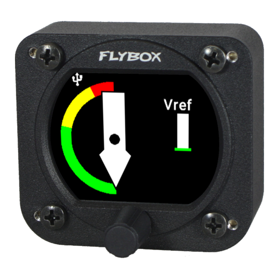
FLYBOX ® Operating Instructions 5.3 USE OF THE INSTRUMENT When switched-ON and the Audio test (if enabled), is done, the display will immediately show the main screen. Speed deviation bar Stall indicator The figure represents the indicator when the aircraft is stationary on the ground. -
Page 46: Stall Indicator
FLYBOX ® 5.4 Stall indicator While cruising or at a speed significantly higher than the stall speed, the indication will be as in the figure. As the stall speed approaches, the white arrow will begin to move towards the yellow section of the arc, upon reaching it, the alarm output will begin to emit tones that will become closer and closer as the arrow moves towards the red arc. -
Page 47: Vref Speed Deviation Bar
FLYBOX ® 5.5 Vref Speed Deviation Bar The indicator on the right of the screen shows in graphic form the deviation of the current speed from the speed entered in the Vref field. When the current speed is exactly equal to the Vref, the... -
Page 48: Vemax Speed Deviation Bar
FLYBOX ® 5.6 VeMax Speed Deviation Bar The indicator on the right of the screen shows in graphic form the deviation of the current speed from the speed entered in the VeMax field. When the current speed is exactly equal to the VeMax,... -
Page 49: Logger
FLYBOX ® Operating Instructions 5.7 Logger The Logger can be useful for storing flight data on the USB stick, for example to ask for assistance in case of problems. The data will be stored at 1 second samples and written on a file with some information of the instrument that generated them. -
Page 50: Technical Specifications
● ASI input range: 0-500 km/h ● Open-collector alarm output (max 300mA, active low). This output can also be used to send a tone in the intercom, using the Flybox optional device code 105899. ● Operating temperature range: -20 ~ +70°C. -
Page 51: Warranty
Products is not intended to be used. Flybox®, after verification of the complaint and confirmation that the defect is covered by warranty, at its sole discretion, will either replace or repair the Products at no costs for the customer. -
Page 52: Term Of Use And Disclaimer
FLYBOX ® Disclaimer Term of Use and Disclaimer Limitation of Liability In no event shall MICROEL s.r.l. be liable for any direct, indirect, punitive, incidental, special consequential damages whatsoever arising out of or connected with the use or misuse of its products. - Page 53 WARNING: All photos, data, drawings, instruments layouts, technical solutions and data representation you find in this document or watching at FLYBOX® instruments working and/or you can access by means of any other media, including web sites, are sole property of MICROEL s.r.l., cannot be copied or imitate without a written permission of MICROEL s.r.l.
- Page 54 Page Intentionally Left Blank...
- Page 55 Page Intentionally Left Blank...
- Page 56 Flybox® is a registred brand of Microel s.r.l.- Italy www.flyboxavionics.it MICROEL s.r.l. Via Mortara 192-194 27038 Robbio (PV) - ITALY Tel +39-0384-670602 - Fax +39-0384-671830...
Need help?
Do you have a question about the Omnia57-80 Series and is the answer not in the manual?
Questions and answers