Table of Contents
Advertisement
Quick Links
User Manual
PCE-SLT Sound Level Meter
(Including Transmitter PCE-SLT-TRM)
User manuals in various languages (français,
italiano, español, português, nederlands, türk, polski,
русский, 中文) can be found by using our
product search on: www.pce-instruments.com
Last change: 31 January 2024
v1.0
© PCE Instruments
Advertisement
Table of Contents

Related Manuals for PCE Instruments PCE-SLT


Summary of Contents for PCE Instruments PCE-SLT
- Page 1 User Manual PCE-SLT Sound Level Meter (Including Transmitter PCE-SLT-TRM) User manuals in various languages (français, italiano, español, português, nederlands, türk, polski, русский, 中文) can be found by using our product search on: www.pce-instruments.com Last change: 31 January 2024 v1.0 © PCE Instruments...
-
Page 2: Table Of Contents
10.7 Offset ..........................9 10.8 Gain setting ........................9 10.9 Set RS232 unit ........................10 11 RS232 ....................11 11.1 RS232 settings ........................11 11.2 RS232 protocol .......................12 12 Reset system ..................12 13 Contact ....................12 14 Disposal ....................12 © PCE Instruments... -
Page 3: Safety Notes
Please read this manual carefully and completely before you use the device for the first time. The device may only be used by qualified personnel and repaired by PCE Instruments personnel. Damage or injuries caused by non-observance of the manual are excluded from our liability and not covered by our warranty. -
Page 4: Specifications
92 (+ 0.8) mm x 45 (+ 0.5) mm to DIN Weight approx. 250 g / 0.56 lb Envioronmental conditions max. 80 % RH / 0 ... +50 °C / 32 ... 122 °F Protection class IP 60 © PCE Instruments... -
Page 5: Dimensions
Dimensions © PCE Instruments... -
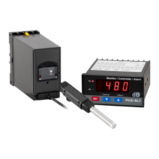
Page 6: Description Transmitter
3.4 Connection to mounting plate 3.5 Fixing holes for wall mounting 3.6 Sensor connection (male) 3.7 Sensor 3.8 Transmitter cover 3.9 Setting the measured value ranges 3.10 Light (measured value too low) 3.11 Light (measured value too high) © PCE Instruments... -
Page 7: Display Description
Display description 3.1 Display 3.2 Measured value display (indicator) 3.3 Value set display (indicator) 3.4 SET key 3.5 Decrease key 3.6 Increase key 3.7 Control display 3.8 Alarm display 3.9 Terminal strip 3.10 Mounting bracket 3.11 RS232 interface © PCE Instruments... - Page 8 T1 - T2 Power supply T3 - T4 Control relay T5 - T6 Alarm relay T7 - T8 Power supply 24 VDC T9 - T14 Not connected T15 - T16 4 ... 20 mA interface © PCE Instruments...
-
Page 9: Initial Commissioning
Then connect the transmitter to the connection terminal. Finally, connect the sensor to the transmitter. Note: For the 24 V version of the transmitter (PCE-SLT-TRM-24V), ensure that the supply ground is galvanically isolated from the signal ground. Connecting the display First mount the display using the mounting bracket. -
Page 10: Advanced Menu
“dPSt" appears on the display. Now press the "SET" key four times. “CtHY" now appears on the display. Now press the arrow keys to access this configuration mode and to change the parameterisation for the hysteresis. Press the "SET" key to save the setting. © PCE Instruments... -
Page 11: Hysteresis For The Alarm Function
Now press the "SET" key seven times. “GAin" now appears on the display. Now press the arrow keys to access this configuration mode and to change the parameterisation for the gain. Press the "SET" key to save the setting. © PCE Instruments... -
Page 12: Set Rs232 Unit
95 = cm/s 30 = COUT 63 = VA 96 = inch 31 = Hz 64 = KVA 97 = FtS2 32 = DEG 65 = KWHr 98 = in/s Press the "SET" key to save the setting. © PCE Instruments... -
Page 13: Rs232
RS232 The PCE-SLT has an RS232 interface that can be connected via a 3.5 mm jack. The jack plug must be constructed as follows: 11.1 RS232 settings To receive the data correctly, set the COM connection on your PC as follows:... -
Page 14: Rs232 Protocol
For countries outside the EU, batteries and devices should be disposed of in accordance with your local waste regulations. If you have any questions, please contact PCE Instruments. © PCE Instruments... - Page 15 PCE Instruments contact information Germany France Spain PCE Deutschland GmbH PCE Instruments France EURL PCE Ibérica S.L. Im Langel 26 23, rue de Strasbourg Calle Mula, 8 D-59872 Meschede 67250 Soultz-Sous-Forets 02500 Tobarra (Albacete) Deutschland France España Tel.: +49 (0) 2903 976 99 0 Téléphone: +33 (0) 972 3537 17...
Need help?
Do you have a question about the PCE-SLT and is the answer not in the manual?
Questions and answers